 English▼


products categories
- Battery Production Equipment Line
- Battery Lab Pilot Equipment Line
- Lithium Battery Pack Assembly Line
- Solid State Battery Assembly Line
- Sodium Ion Battery Production Line
- Supercapacitor Assembly Line
- Lithium Ion Battery Recycling Plant
- Dry Electrode Preparation Solution
- Perovskite Based Solar Cell Lab Line
- Li ion Battery Materials
- Cathode Active Materials
- Anode Active Materials
- Customized Battery Electrode
- Coin Cell Parts
- Lithium Chip
- Cylindrical Cell Parts
- Battery Current Collectors
- Battery Conductive Materials
- Electrolyte
- Metal Mesh
- Battery Binder
- Separator and Tape
- Aluminum Laminate Film
- Nickel Strip
- Battery Tabs
- Graphene Materials
- Nickel Felt
- Titanium Fiber Felt
- Battery
- Battery Pack Machine & Compoments
- Battery Pack Compoments
- Turnkey Solutions Battery Pack Assembly Line
- Cell Sorter
- Battery Pack Spot Welder
- Laser Welder
- Battery Charging Discharging Tester
- Battery Pack Aging Machine
- Battery Pack Comprehensive Tester
- CCD Visual Inspector
- Battery Pape Sticking Machine
- BMS Testing Machine
- Al Wire Bonding Machine
- Lithium Battery Machine
- Battery Tester & Analyzer
- Battery Safety Tester
- Material Characterization Tester
- Rolling Press Machine
- Spot Welding Machine
- Vacuum Mixer Machine
- Crimping/Disassembling Machine
- Vacuum Sealing Machine
- Electrolyte Filling
- Stacking/Winding Machine
- Electrode Cutter/Slitter
- Pouch Forming Machine
- NMP Solvent Treatment System
- Lithium Battery Production Plant
- Vacuum Glove Box
- Furnaces
- Coaters
- PVD Coater
- Laboratory Press Machine
- Large Press Machine
- Planetary Centrifugal Mixer
- Ball Mill
- Laboratory Machine
- Cutting Machine
- Metal Foam
contact us
- If you have questions, please contact us, all questions will be answered
- WhatsApp : +86 18659217588
- Email : David@tmaxcn.com
- Email : Davidtmaxcn@gmail.com
- Add : No. 39, Xinchang Road, Xinyang, Haicang Dist., Xiamen, Fujian, China (Mainland)
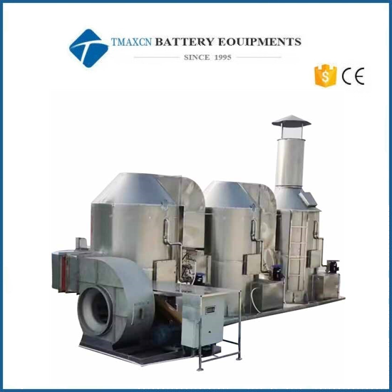
Automatic Low-Emission 5000 m³/h NMP Solvent Recovery System
Model Number:
TMAX-GT-5000FLCompliance:
CE CertifiedWarranty:
One year limited warranty with lifetime technical supportPayment:
L/C D/A D/P T/T Western UnionDelivery Time:
5 days
- WhatsApp : +86 18659217588
- Email : David@tmaxcn.com
- Email : Davidtmaxcn@gmail.com
- Wechat : 18659217588
Previous:
9000 m³/h NMP Exhaust Gas Treatment System for Lithium Battery ProductionNext:
Low-Emission 4000 m³/h NMP Solvent Recovery System for Battery Production
5000 m³/h Automatic NMP Solvent Recovery Machine
I. System Function
This series of NMP recovery units utilizes the property that NMP is fully miscible with water to recover and treat exhaust gas emitted from coating machines. The system operates fully automatically to ensure operational stability and safety. It adopts a three-stage segmented spray absorption design, with final emissions significantly lower than national standards.
The system is composed of: ventilation ducts, recovery towers, pump units, blower, NMP liquid storage tank, and control system. The recovery unit offers high efficiency, low operational costs, compact footprint, appealing appearance, and superior performance. It is suitable for various environments and installation layouts, with simple operation, making it ideal for the coating processes of multiple lithium battery production lines.
II. System Configuration
1. Air Handling Capacity: 5000 m³/h
Model: TMAX-GT-5000FL
Environmental Standard: GB 30484-2013 Emission Standard of Pollutants for the Battery Industry (non-methane total hydrocarbon concentration limit)
2. Main Unit Color: SUS gray
3. Functional Module Overview:
No. |
Module |
Function Description |
1 |
Recovery Tower |
Recovers NMP vapor and achieves compliant emissions through water spray adsorption |
2 |
Pump Unit |
Circulates and discharges water within the recovery tower |
3 |
Blower |
Delivers air to the recovery tower and maintains positive pressure in the coater |
4 |
Storage Tank |
Stores recovered NMP waste liquid |
5 |
Control System |
Automates operation between the recovery unit and the coater, maintaining stable oven and exhaust concentrations |
4. Delivery List:
No. |
Equipment Name |
Model |
Quantity |
Remarks |
1 |
Recovery Tower |
TMAX-GT-5000FL |
1 set |
SUS304 |
2 |
Blower |
3KW |
1 unit |
Intelligent frequency control |
3 |
Control Cabinet |
NMP5K-1 |
1 set |
Local + Remote Control |
4 |
Water Pump |
1.5KW |
3 units |
Chemical pipeline pump |
5 |
Storage Tank |
2m³ |
1 unit |
SUS201 |
6 |
Discharge Pump |
0.35KW |
1 unit |
Corrosion-resistant pump |
5. Main Components – 4000 Air Volume NMP Recovery System: (Applicable here as shared model)
No. |
Component |
Specification |
Quantity |
Remarks |
1 |
Tower Body |
∅1.0m × H3.0m |
3 units |
SUS304 |
2 |
Corrugated Packing |
φ1.0m × 20mm × 3 layers × 0.3mm |
3 sets |
SUS304 |
3 |
Wire Mesh Packing |
φ1.0m × 20mm |
1 set |
SUS304 |
4 |
Water Pump |
1.5KW |
3 units |
In-tank pumps |
5 |
Online Concentration Detector |
CM-800α |
1 set |
SZTMAX |
6 |
Exhaust Fan |
3KW |
1 unit |
Guangzhou XinFeng |
7 |
Frequency Converter |
3KW |
1 unit |
V&T |
8 |
Control Cabinet |
System Integrated |
1 set |
Q235, Outdoor |
9 |
Liquid Circulation Piping |
System Integrated |
1 set |
SUS304 |
10 |
Storage Tank |
2m³ |
1 unit |
SUS201 |
11 |
Liquid Level Alarm |
- |
1 set |
TMAX |
12 |
Discharge Pump |
0.35KW |
1 unit |
Corrosion-resistant |
III. Design Basis and Reference Standards
1. Complies with national, industry, and local regulations as well as client requirements.
2. Uses energy-efficient and easy-to-implement treatment methods to minimize power usage, capital investment, footprint, and operational complexity.
3. All mechanical and electrical components are selected from well-known, reputable brands to ensure reliability.
4. The system does not produce secondary pollution during construction or operation.
IV. Design Parameters
Item |
Value |
System Model |
TMAX-GT-5000FL |
Max Exhaust Treatment Volume |
5000 m³/h |
Single Tower Dimension |
∅1.0m × H3.0m |
Power Supply |
380V / 3 Phase / 50Hz |
Installed Power |
7.5KW (4.5KW pumps + 3KW fan) |
Operating Weight |
2 tons |
Floor Load Capacity |
500 KG/m² |
NMP Recovery Efficiency |
≥ 99.6% |
Recovered NMP Concentration |
Adjustable 80%–90% |
Tail Gas Emission Concentration |
< 50 mg/m³ |
Soft Water Consumption |
≤ 0.05 m³/h |
Installation Dimensions |
7m (L) × 2m (W) |
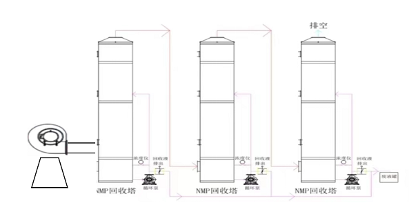
V. Equipment Process Flow
1. Process Flow Diagram: (Image for reference only)
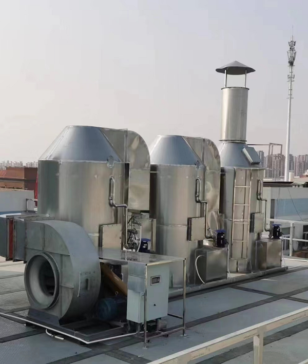
2.Installation Diagram: (Image for reference only)
VI. Working Principle of NMP Recovery Tower
1. The system recovers NMP by absorbing it into pure water. Waste gas enters from the bottom of the tower and passes through an adsorption unit where NMP dissolves into water and vapor. After treatment, the gas passes through a gas-liquid separator and a top rinsing stage to ensure complete NMP capture.
2. Because of the high temperature of the inlet gas, energy exchange during recovery causes some water evaporation. A circulation pump redirects liquid from within the tower back to the adsorption unit for reuse, enabling effective heat recovery, reducing water waste, and improving NMP concentration in the recovered liquid. Treated exhaust gas can be directly vented with near-zero emission.
3. Structure of the Tower:
The tower is composed of three key functional sections:
Spray Heat Exchange Zone: Allows rapid mass and heat exchange between NMP vapor and water. Direct contact eliminates heat transfer wall resistance, ensuring high efficiency.
Mass Transfer Separation Zone: Uses high-efficiency structured packing (specific surface area 140Y). Liquid flows downward while NMP gas rises in countercurrent, ensuring effective capture of vapor droplets.
Demisting Zone:
Lower demister uses baffles and inertia to remove droplets; airflow is zigzagged to force collection.
Upper demister forms spiral airflow that throws droplets to the sides into collection channels.
Demisting efficiency: 90%–99%.
VII. Control System
1. Electrical Panel Components:
No. |
Component |
Brand |
Qty |
Remarks |
1 |
Electrical Components |
Chint |
1 set |
|
2 |
Frequency Converter |
V&T |
1 set |
|
3 |
NMP Liquid Sensor |
Local |
1 set |
With lens cleaning unit |
4 |
Valves |
Local |
1 set |
|
2. System Control Description:
No. |
Item |
Technical Specification |
1 |
Main Control Unit |
Independent outdoor cabinet; remote start/stop near coater |
2 |
Operating Modes |
Manual, automatic, emergency stop, remote control |
3 |
Waste Liquid Monitoring |
Real-time display and configurable settings |
4 |
Alarms |
Sound and light alarms at coater; buzzer at outdoor cabinet |
5 |
Safety Protection |
Temperature alarm and power-off protection features |


 +86 13174506016
 David@tmaxcn.com

