 ru
ru
products categories
- Battery Production Equipment Line
- Battery Lab Pilot Equipment Line
- Lithium Battery Pack Assembly Line
- Solid State Battery Assembly Line
- Sodium Ion Battery Production Line
- Supercapacitor Assembly Line
- Lithium Ion Battery Recycling Plant
- Dry Electrode Preparation Solution
- Perovskite Based Solar Cell Lab Line
- Li ion Battery Materials
- Cathode Active Materials
- Anode Active Materials
- Customized Battery Electrode
- Coin Cell Parts
- Lithium Chip
- Cylindrical Cell Parts
- Battery Current Collectors
- Battery Conductive Materials
- Electrolyte
- Metal Mesh
- Battery Binder
- Separator and Tape
- Aluminum Laminate Film
- Nickel Strip
- Battery Tabs
- Graphene Materials
- Nickel Felt
- Titanium Fiber Felt
- Battery
- Battery Pack Machine & Compoments
- Battery Pack Compoments
- Turnkey Solutions Battery Pack Assembly Line
- Cell Sorter
- Battery Pack Spot Welder
- Laser Welder
- Battery Charging Discharging Tester
- Battery Pack Aging Machine
- Battery Pack Comprehensive Tester
- CCD Visual Inspector
- Battery Pape Sticking Machine
- BMS Testing Machine
- Al Wire Bonding Machine
- Lithium Battery Machine
- Battery Tester & Analyzer
- Battery Safety Tester
- Material Characterization Tester
- Rolling Press Machine
- Spot Welding Machine
- Vacuum Mixer Machine
- Crimping/Disassembling Machine
- Vacuum Sealing Machine
- Electrolyte Filling
- Stacking/Winding Machine
- Electrode Cutter/Slitter
- Pouch Forming Machine
- NMP Solvent Treatment System
- Lithium Battery Production Plant
- Vacuum Glove Box
- Furnaces
- Coaters
- Hydraulic Press
- Ball Mill
- Planetary Centrifugal Mixer
- Cutting Machine
- Laboratory Machine
- Metal Foam
contact us
- If you have questions, please contact us, all questions will be answered
- WhatsApp : +86 13174506016
- Email : David@tmaxcn.com
- Email : Davidtmaxcn@gmail.com
- Add : No. 39, Xinchang Road, Xinyang, Haicang Dist., Xiamen, Fujian, China (Mainland)
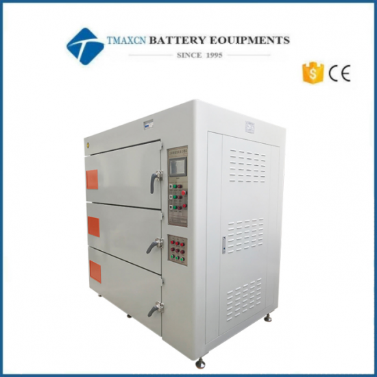
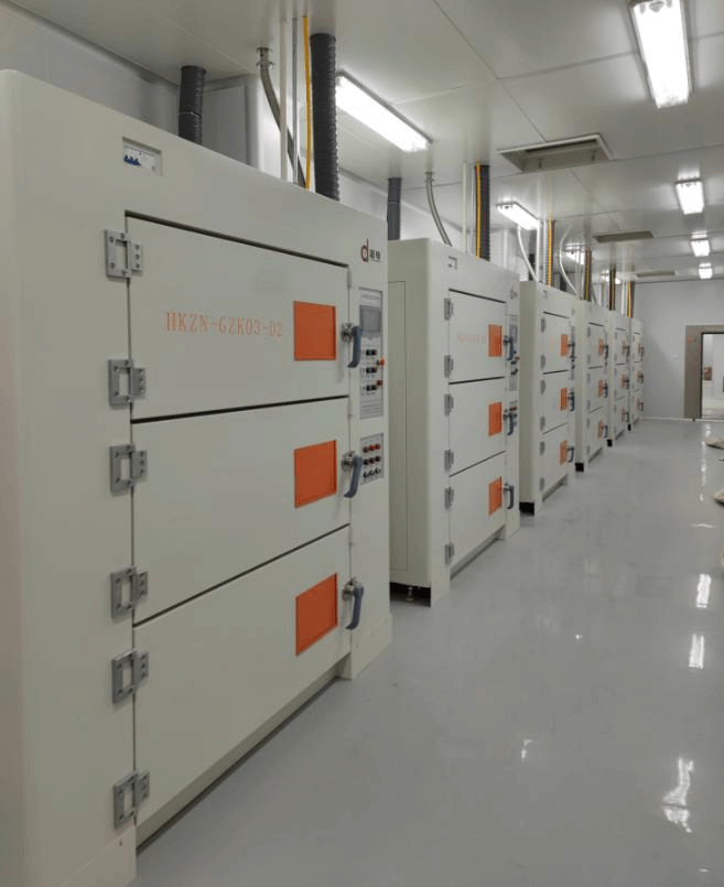
Three-Layer Double-Door Intelligent High Vacuum Oven
Model Number:
TMAX-HKZN-GZK03-D2Type:
AutomaticCompliance:
CE CertifiedWarranty:
One year limited warranty with lifetime technical supportPlace of Origin:
ChinaPayment:
L/C D/A D/P T/T Western UnionDelivery Time:
45 days
- WhatsApp : +86 13174506016
- Email : David@tmaxcn.com
- Email : Davidtmaxcn@gmail.com
- Wechat : 18659217588
Previous:
Three-Layer Single-Door Energy-Saving Vacuum OvenNext:
500L Planetary Vacuum Mixing Machine
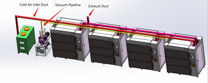
Equipment Series: High Vacuum Series – One-to-Four Configuration
Applicable Products: Battery, Cell, Electrode Sheet Baking
Internal Chamber Dimensions: Height 350mm × Width 850mm × Depth 1250mm (× 3 units)
External Dimensions: Height 2150mm × Width 2000mm × Depth 1400mm
I. Basic Structure
Consists of eight parts:
1. Frame Section;
2. Internal Chamber Section;
3. Vacuum and Nitrogen Charging Section;
4. Electrical Control Section;
5. External Circulation Section;
6. Internal Circulation Section;
7. Double-Door Interlock Section;
8. Cooling System Section (Optional Configuration)
II. Process Flow Diagram
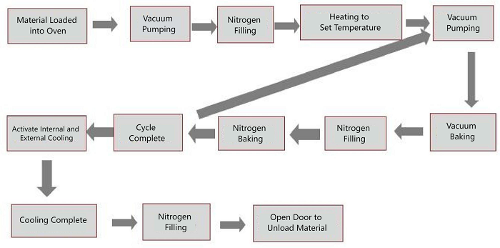
III. Product Overview
The high vacuum oven is used for moisture removal baking of lithium battery cells and electrode sheets. Compared with conventional ovens, it has advantages of stable performance, high vacuum level, short baking time, excellent dewatering and drying effect, and good pressure retention. It is combined with a dedicated high vacuum unit and cooling system to form an independent baking system, replacing conventional traditional ovens.
IV. Working Principle
Each machine can operate in continuous cycles; the basic process: open the door, place the cells or electrode sheets into the oven, then set the heating time, vacuum time, and nitrogen time. The system will automatically complete heating and timed gas exchange according to the preset time parameters, completing the baking process.
V. Product Features
High Vacuum Design |
The internal chamber is made using pressure vessel standard welding process, with high vacuum retention, long durability, and no deformation. |
Stable Temperature Uniformity |
Temperature uniformity reaches ±3℃ under constant temperature. |
Optimized Space Design |
The internal chamber size can be customized according to the customer’s battery size, improving space utilization efficiency. |
Precise Temperature Control |
Temperature is controlled using silicon-controlled rectifier (SSR) + PID mode, with low thermal inertia and good control effect. |
Heating Method |
Hot air circulates both inside and outside the chamber, maintaining consistent internal and external chamber temperatures. Heat radiation and heat conduction ensure chamber temperature uniformity. During cooling, heating tubes are shut off, and internal heat is carried away by air circulation, accelerating cooling speed. |
Sixfold Safety Protection |
Ensures operational safety and product reliability. |
Automated Program Control |
PLC program controls heating, vacuuming, and nitrogen injection. Manual/automatic operation modes can be switched. Automatic timed heating is completed by simply setting heating time, vacuum time, and nitrogen time. The system will automatically perform baking and gas exchange. |
Internal Airflow Structure |
Uses magnetofluid circulation with good sealing and high temperature resistance. |
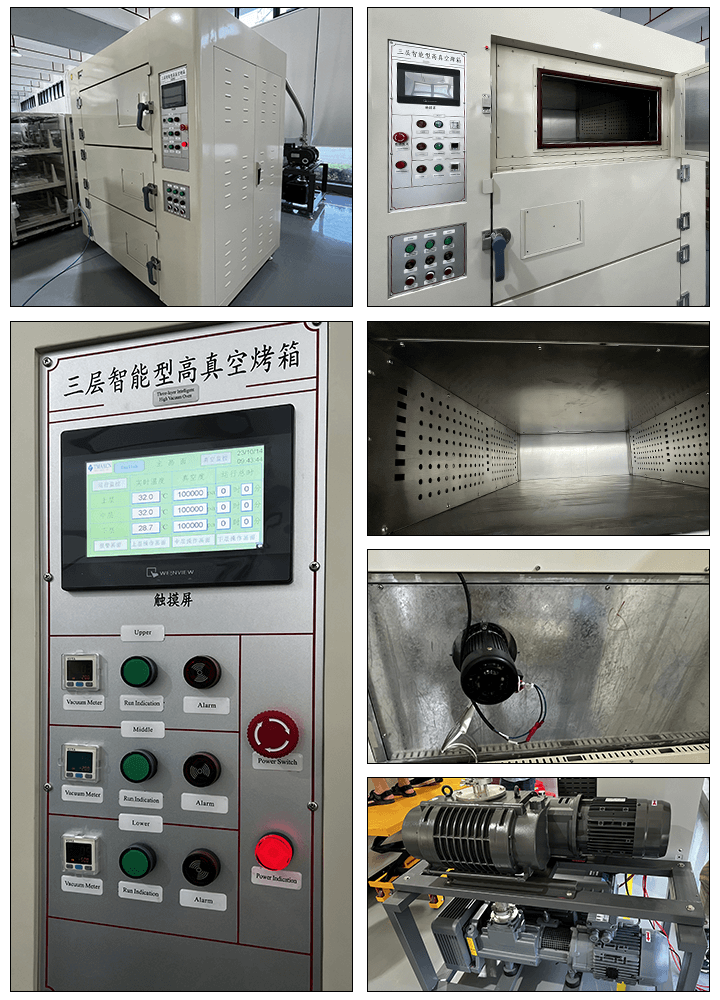
VI. Oven Structure
Internal Chamber Dimensions |
Height 350mm × Width 850mm × Depth 1250mm (× 3 units) |
External Dimensions |
Height 2140mm × Width 2000mm × Depth 1400mm |
Outer Shell Material |
A3 cold-rolled steel plate, coated with baking paint, color: gray-white-orange |
Inner Liner Material |
Industrial brushed stainless steel plate, thickness: 4.5mm |
Door Type |
Double-door |
Inner Liner Sealing Ring |
Molded silicone O-ring, high temperature and corrosion resistant |
Control Mode |
PLC automatic control mode, touch screen operation |
Double-Door Interlock Function |
When one door is opened, the opposite door lights up and locks. Forcibly opening both doors will trigger an alarm and light prompt (effectively prevents cell trays from being pushed through and falling out the other side) |
Vacuum and Nitrogen Charging Port Position and Interface Specifications |
Interface position is at the rear of the equipment; vacuum interface is KF40, dry gas charging interface is φ12mm air pipe interface |
VII. Vacuum and Temperature Control
Vacuum Degree |
No-load chamber vacuum ≤10 Pa, full-load chamber vacuum: 50–100 Pa, leakage ≤500 Pa within 24 hours |
Heating Method |
Dual circulation of air internally and externally, dual heat source dual-control heating via thermal radiation, thermal conduction, and electric heating |
External Heating Structure |
U-shaped airflow; air is discharged from the left, drawn in from the right, with exhaust from top and bottom, achieving temperature uniformity |
Main Heating Temperature Control |
Temperature control accuracy within ±0.5℃ |
Chamber Temperature Deviation |
±3℃ (empty box, constant temperature state) |
Temperature Range |
Room temperature +20℃ to 200℃ |
Heating Rate |
Room temp to 85℃ ≤30 minutes (atmospheric pressure, no load; time for instrument to reach set temperature); internal chamber temperature stabilization time 60–90 minutes (no load); room temp to 85℃ ≤45 minutes (full load); internal chamber temperature stabilization time 90–120 minutes (full load) |
Heating State |
Temperature rises in a curve to the set value, then remains flat during constant temperature phase |
Cooling Method |
Cold air system connected to external airflow duct; alternating conduction cooling from outside the inner liner air duct; internal vacuum nitrogen is used for alternating cooling |
Cooling Time |
≤60 minutes (empty box, from 100℃ to 55℃, measured at core); full-load test time ≈120 min (depending on battery size and capacity) |
Surface Temperature of the Chamber |
When internal temp is 100℃, surface temp ≤ room temperature + 20℃ |
Independent Operation Per Layer |
Each layer independently performs heating, vacuuming, and nitrogen charging |
VIII. System Composition
1. The vacuum oven body mainly consists of sheet metal structure, heating system, circulation fan system, and software control system.
2. The auxiliary cooling system mainly consists of cooling exchange valves, cooling pipelines, and high-pressure fans, which cool the chamber from outside the working chamber.
3. The auxiliary cooling system is shared by three chambers, each independently controlled by valves.
4. The vacuum system consists of vacuum piping.
IX. Electrical Configuration
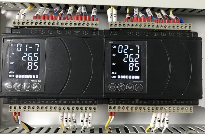
Temperature Controller |
Digital intelligent temperature controller / Microcomputer PID automatic calculation (Shanghai Yatai) |
Temperature Control Mode |
PID + SSR (silicon controlled rectifier) (Shanghai Yatai) |
Over-temperature Protection |
Digital intelligent temperature controller / Microcomputer PID automatic calculation (Shanghai Yatai) |
Temperature Sensor |
K-type thermocouple |
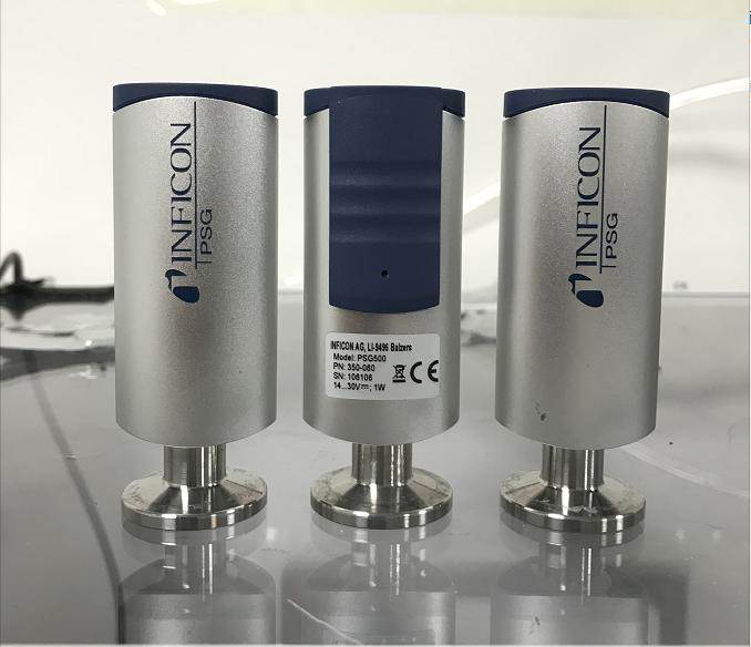
Vacuum Gauge |
INFICON resistance vacuum gauge (Switzerland) |
Vacuum Valve / Gas Inlet Valve |
Customized |
PLC |
Wecon, Fujian |
Touch Screen |
7-inch LED color screen by Wecon |
Independent Alarm Device |
Yijia |
Heating Tube |
Customized |
Leakage Circuit Breaker |
Chint |
Contactor |
Schneider |
Control Mode |
Heating, vacuuming, and gas charging operations are controlled via PLC in automatic circulation mode; all operation stages are set through the touch screen |
INFICON Resistance Vacuum Gauge PSG500
(Mainly used to control and display high vacuum levels)
Shanghai Yatai temperature control module
(mainly controls temperature uniformity to prevent overheating)
X. Safety Protection
1. Chamber over-temperature protection—automatically cuts off power when over-temperature is detected
2. Overcurrent and short circuit protection for heating tube
3. Overcurrent and short circuit protection for internal circulation fan
4. Overcurrent and short circuit protection for control system
5. Special explosion-proof door, pressure-resistant, with overpressure self-release function
6. When the chamber is overcharged, the device can automatically shut off the nitrogen & dry gas inlet to save gas and reduce consumption
7. Independent audio-visual alarm for set time notification
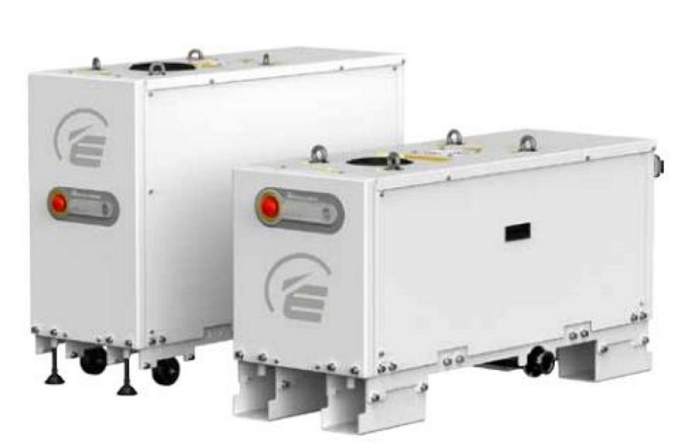
XI. Vacuum System (Edwards GXD1601750, UK)
The vacuum system is provided by the supplier and allows a maximum of 3 chambers to vacuum simultaneously. After reaching the target vacuum level, the corresponding branch valve will automatically close before other chambers start vacuuming.
Technical Data
Parameter |
Unit |
GXS160 |
GXS160/1750 |
|
Peak Pumping Speed |
m³/hr (cfm) |
160 (94) |
1200 (706) |
|
Ultimate Vacuum (without purge) |
mbar (Torr) |
7×10⁻³ (5.3×10⁻³) |
7×10⁻⁴ (5.3×10⁻⁴) |
|
Power |
Ultimate pressure |
kW (hp) |
3.8 (5.1) |
5.1 (6.8) |
Maximum gas ballast |
kW (hp) |
5.0 (6.7) |
7.4 (9.9) |
|
Electrical |
Power supply |
High voltage |
380–460V 3φ 50/60Hz |
|
Low voltage |
200–230V 1φ 50/60Hz |
|||
Connection |
High voltage |
Harting Han K 4/4-F |
||
Low voltage |
||||
Vacuum Connection |
Inlet |
|
ISO63 |
ISO100 |
Outlet |
|
NW40 |
||
Cooling Water |
Max supply pressure |
bar (psig) |
6.9 (100) |
|
Min inlet/outlet pressure difference |
bar (psig) |
1.0 (14.7) |
||
Min flow at pressure |
l/min (gal/min) |
4.0 (1.1) |
7.0 (1.9) |
|
Temperature |
°C (°F) |
5–40 (41–104) – All models |
||
Connection |
|
3/8" BSP Female (G 3/8") |
||
Purge Gas* |
Pressure |
bar (psig) |
2.5–6.9 (36–100) |
|
|
Light load |
sl/min |
12 |
|
|
Medium load |
sl/min |
18-52 |
|
|
Connection |
|
Swagelok® Ø 1/4" Tube, with Ferrule Connector |
|
Process Gas Purge / Solvent Flush |
Gas Inlet Pressure |
bar (psig) |
2.5–6.9 (36–100) |
|
Control valve connection |
|
Swagelok® Ø 3/8" Tube, with Ferrule Connector |
||
Filter connection |
|
1/2" NPT Female Thread |
||
Solvent connection |
|
3/8" BSP Female Thread (G 3/8") |
||
Weight |
Kg (lbs) |
305 (672) |
475 (1047) |
|
Noise (with suitable exhaust pipe) |
dB(A) |
<64 |
||
Operating Temperature |
°C (°F) |
5–40 (41–104) |
||
Max Allowable Exhaust Pressure |
mbar (psia) |
1400 (20) |
||
System IP Rating |
Standard |
31 |
||
Lubricant |
Type |
PFPE Drynert® 25/6 |
||
Capacity |
l (gal) |
0.7 (0.2) |
1.4 (0.4) |
|
Monitoring & Control |
Standard Model |
Control |
Internal controller "Dashboard" Interface – RS232 |
|
Monitoring |
Ethernet Web Interface |
|||
Optional Model |
Control |
Parallel – MCM MicroTIM |
||
Control & Monitoring |
Profibus DP Display Terminal (PDT) |
|||
Monitoring |
FabWorks* |
|||
Pump |
Light Load |
shaft seal purge only |
||
Medium Load |
Shaft seal purge, high vacuum purge, inlet purge, variable valve & exhaust purge(with exhaust pressure sensor) |
|||
Medium Load+ |
Same with medium load, plus high-flow gas purge, solvent purge |
|||
1. Ultimate Vacuum Degree: ≤10 Pa (no-load condition); single chamber reaches 10 Pa from atmospheric pressure ≤10 min (no-load condition)
2. Vacuum Leakage Rate (cold, no-load condition): After reaching ultimate vacuum and closing the valve, hold for 1 hour; average vacuum drop ≤20 Pa. After 24 hours, vacuum drop ≤500 Pa (i.e., ≤20 Pa/h)
3. Vacuum system adopts a single-pump multi-chamber layout for vacuuming; no-load ultimate vacuum ≤10 Pa. The actual vacuum level changes depending on the gas emission from the items being vacuumed.
¢ High vacuum range: 50–100 Pa (efficient for dewatering)
¢ Low vacuum range: ≤–20 kPa (nitrogen exchange threshold)
4. System Composition: Includes a two-stage vacuum pump and vacuum pipeline; the pump can be self-supplied or provided by the supplier
5. Pipeline Arrangement: Based on the contract-confirmed drawings and layout between vacuum pump and oven; short-distance vacuum bellows are supplied by the supplier. For additional pipeline installation, confirmation and a designated installer are required in advance.
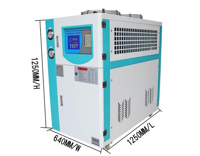
XII. Chiller Parameters (Air-Cooled Chiller, 5HP, for Vacuum Pump Cooling Use)
Chiller Parameters Table:
Specification Table for XC-6HP Air-Cooled Chiller Unit
No. |
Item |
Specification Type |
Performance Parameter |
1 |
Unit |
Model |
XC-6HP |
2 |
Cooling Capacity |
kW |
16.9 (Outlet Water Temp. 10°C, Condensing Temp. 50°C) |
Kcal/h |
14560 (Outlet Water Temp. 10°C, Condensing Temp. 50°C) |
||
3 |
Power Supply |
V |
5N-380-50HZ |
4 |
Control Method |
Type |
Capillary Tube |
5 |
Total Power |
A |
5.63 |
6 |
Compressor |
Type |
Fully Enclosed Scroll Type |
Cooling Input Power (kW) |
4.5 |
||
Type |
Scroll Type |
||
7 |
Fan |
Type |
Outer Rotor Axial Flow Fan |
Power (kW) |
0.38 |
||
Air Volume (m³/h) |
7000 |
||
8 |
Water Pump |
Type |
Centrifugal Clean Water Pump |
Power (kW) |
0.75 |
||
Lift (m) |
28 |
||
Flow Rate (L/min) |
100 |
||
9 |
Condenser |
Type |
Aluminum Fin Coil with Copper Tube |
Cooling Air Volume |
6000 |
||
10 |
Evaporator |
Type |
Coil Type |
Water Volume (m³/h) |
2.91 |
||
Water Holding Volume (m³) |
0.065 |
||
11 |
Water Tank |
Material |
SUS304 |
Capacity (L) |
56 |
||
12 |
Piping |
Chilled Water Outlet |
DN25 (based on customer requirement) |
Chilled Water Inlet |
DN25 (based on customer requirement) |
||
Drain Port |
PVC DN20 (based on customer requirement) |
||
Tap Water Inlet |
DN15 (based on customer requirement) |
||
13 |
Microcomputer Controller |
Display |
Button + LED Display |
Output |
30500A |
||
Output Mode Selection |
Solid-state Relay Output |
||
Temp. Control Range (°C) |
+5 ~ +35 |
||
Temp. Accuracy (°C) |
±2.0 |
||
14 |
Alarm Device |
Temp. Abnormal Alarm |
Circulating water temp. too low alarm, cut off compressor |
Power Phase Reverse |
Phase detection protection for pump/compressor reversal |
||
High/Low Pressure Fault |
Pressure switch detects refrigeration system pressure status |
||
Compressor Overload |
Thermal relay protects compressor |
||
Compressor Overheat |
Internal protection device for compressor |
||
Pump Overload |
Thermal relay protection |
||
Low Water Level Alarm |
Float switch |
||
Short Circuit |
Air switch |
||
Refrigerant |
R22 (or chilled water medium) |
||
15 |
External Dimensions |
L×W×H (mm) |
1250×640×1250 |
16 |
Total Unit Weight |
KG |
210 |
XIII. Power
9.1) Power Supply: 400V / 50Hz, 3-phase 5-wire system
9.2) Total Power per Unit: 24 KW
9.3) Vacuum System Power: 10.5 KW
9.4) Cooling System Power: 5 KW
9.5) Cooling System Power: 5 KW
9.6) Equipment Weight: Approximately 1800 kg
XIV. Installation Conditions
12.1 The front of the oven must be at least 1500 mm away from the wall, and the distance from both sides and the rear must be no less than 300 mm.
12.2 Installation site conditions (to be provided by the customer):
12.2.1 Power Supply: Three-phase AC 400±30V, frequency: 50±1Hz; the user must provide an independent power switch and be responsible for the external electrical connection of the equipment.
12.2.2 Compressed Air: Pressure 0.6–0.7 MPa, φ8 air tube
12.2.3 Nitrogen: Pressure 0.1–0.2 MPa, nitrogen pipeline φ12 air tube
12.3 Energy Consumption:
12.3.1 Maximum: ≤24 kWh (excluding vacuum pump and cooling system)
12.3.2 Average: ≤6 kWh (excluding vacuum pump and cooling system)
12.3.3 Environmental Requirements:
l Temperature: -5~35℃
l Humidity: ≤40%
l No flammable, explosive gases, liquids, or solids present in the surrounding environment
l Absolutely prohibited to bake flammable items, combustible gases, or explosive materials inside the oven
XV. System Assembly Plan (Diagram)
This system supports a one-to-four configuration, i.e., 4 sets of high vacuum ovens, 1 set of high vacuum unit, and 1 set of auxiliary cooling system (optional). See the diagram below:
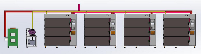
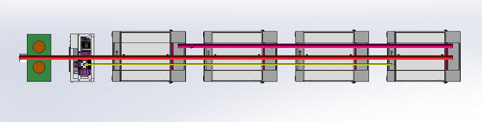

![]()


 Iris@tmaxcn.com
 David@tmaxcn.com
 +86 13174506016
