 ru
ru
products categories
- Battery Production Equipment Line
- Battery Lab Pilot Equipment Line
- Lithium Battery Pack Assembly Line
- Solid State Battery Assembly Line
- Sodium Ion Battery Production Line
- Supercapacitor Assembly Line
- Lithium Ion Battery Recycling Plant
- Dry Electrode Preparation Solution
- Perovskite Based Solar Cell Lab Line
- Li ion Battery Materials
- Cathode Active Materials
- Anode Active Materials
- Customized Battery Electrode
- Coin Cell Parts
- Lithium Chip
- Cylindrical Cell Parts
- Battery Current Collectors
- Battery Conductive Materials
- Electrolyte
- Metal Mesh
- Battery Binder
- Separator and Tape
- Aluminum Laminate Film
- Nickel Strip
- Battery Tabs
- Graphene Materials
- Nickel Felt
- Titanium Fiber Felt
- Battery
- Battery Pack Machine & Compoments
- Battery Pack Compoments
- Turnkey Solutions Battery Pack Assembly Line
- Cell Sorter
- Battery Pack Spot Welder
- Laser Welder
- Battery Charging Discharging Tester
- Battery Pack Aging Machine
- Battery Pack Comprehensive Tester
- CCD Visual Inspector
- Battery Pape Sticking Machine
- BMS Testing Machine
- Al Wire Bonding Machine
- Lithium Battery Machine
- Battery Tester & Analyzer
- Battery Safety Tester
- Material Characterization Tester
- Rolling Press Machine
- Spot Welding Machine
- Vacuum Mixer Machine
- Crimping/Disassembling Machine
- Vacuum Sealing Machine
- Electrolyte Filling
- Stacking/Winding Machine
- Electrode Cutter/Slitter
- Pouch Forming Machine
- NMP Solvent Treatment System
- Lithium Battery Production Plant
- Vacuum Glove Box
- Furnaces
- Coaters
- Hydraulic Press
- Ball Mill
- Planetary Centrifugal Mixer
- Cutting Machine
- Laboratory Machine
- Metal Foam
contact us
- If you have questions, please contact us, all questions will be answered
- WhatsApp : +86 18659217588
- Email : David@tmaxcn.com
- Email : Davidtmaxcn@gmail.com
- Add : No. 39, Xinchang Road, Xinyang, Haicang Dist., Xiamen, Fujian, China (Mainland)
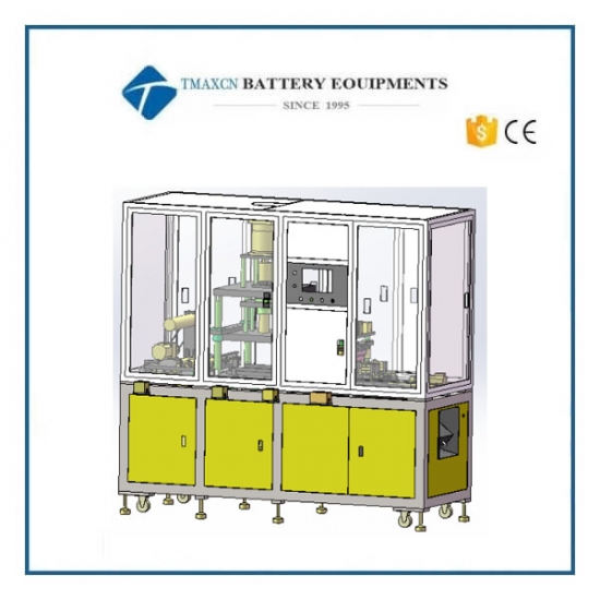
Automatic Pouch Cell Case Forming Machine
Model Number:
TMAX-LDCK-550Compliance:
CE CertifiedWarranty:
Two years limited warranty with lifetime technical supportPayment:
L/C D/A D/P T/T Western UnionDelivery Time:
5 days
- WhatsApp : +86 18659217588
- Email : David@tmaxcn.com
- Email : Davidtmaxcn@gmail.com
- Wechat : 18659217588
Previous:
3 in 1 Automatic Pouch Cell Edge Trimming Ironing Folding Machine(400)Next:
Automatic Pouch Cell Rotary Top and Side Hot Sealing Machine
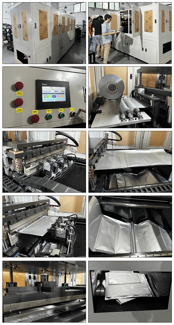
Automatic Pouch Cell Case Forming Machine
1. Equipment Overview
1.1 Equipment Functions and Working Principle
■ Equipment Functions:
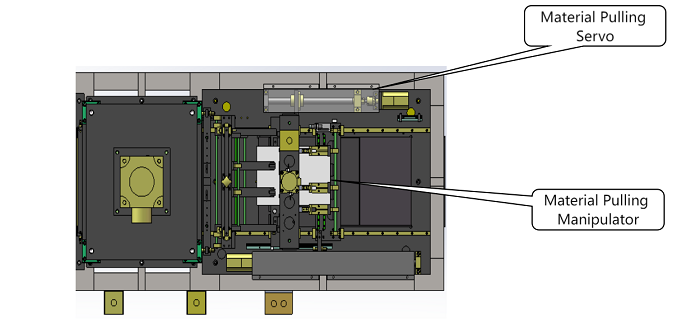
1.1.1 Servo motor drives manipulator to pull material. Pulling length (700 mm) is precisely adjustable.
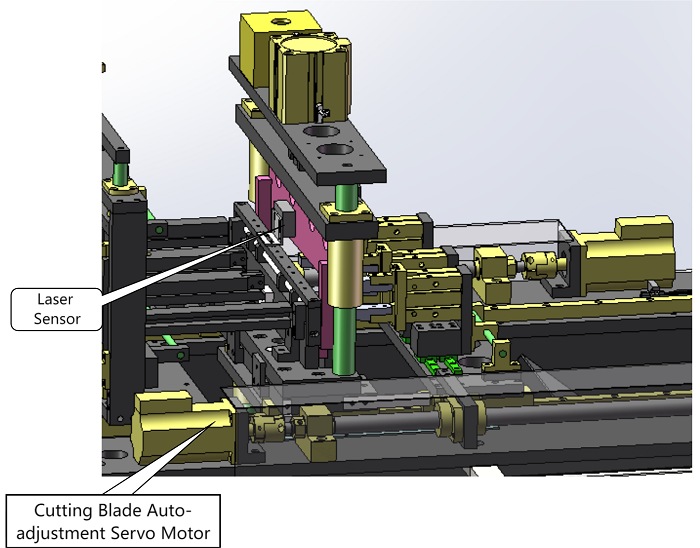
1.1.2 Cutter movement is laser-sensor guided. Servo-driven self-adjustment ensures trimming accuracy ± 0.15 mm. (Lead screw covers full cutter stroke, supports cell body length 60 mm – 280 mm)
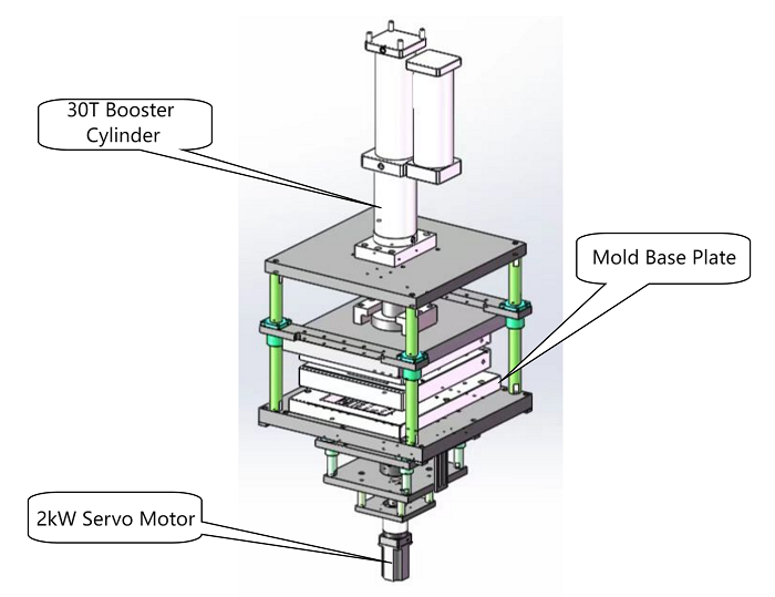
1.1.3 Stamping section (upper platen driven by 30T booster cylinder to press film; after pressing, 2KW servo motor drives forming core upward to complete pocket forming). Diagram as below:
■ Working Principle:
Speed-regulating motor drives air shaft unwinding. PLC controls servo forming. Servo motor drives manipulator to pull material.
1.1 Equipment Operation Flow
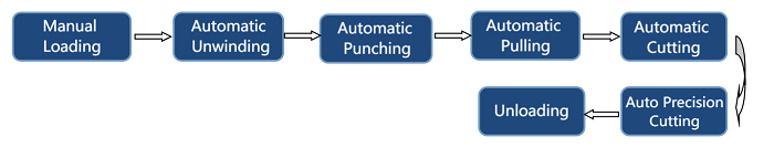
1.2.1 Feeding manipulator clamps material and transfers to designated position based on system settings.
1.2.2 Upon reaching position, 30T booster cylinder drives upper mold to close and maintain pressure. Lower servo motor rises, driving punch to perform deep drawing.
1.2.3 After forming, punch descends. 30T booster cylinder lifts upper mold.
1.2.4 Motor-driven transfer mechanism shifts material by fixed distance.
1.2.5 When material reaches required cutting length, cutter servo moves to position. Cylinder drives cutter downward to cut, ensuring top sealing precision.
1.2.6 Transfer mechanism resets. Next cycle begins.
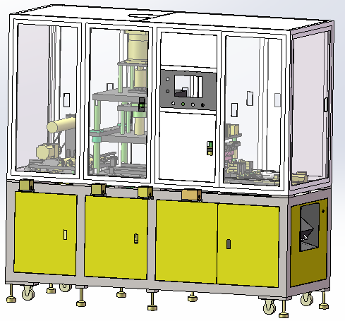
1.3 Overall Structure
Machine dimensions: L 3200 mm × W 850 mm × H 1980 mm, for reference only.
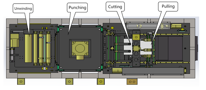
1.4 Main Components (with diagrams)
1.4.1 Feeding Section
1. Floating roller tension device. Material rollers made of plastic steel.
2. Fiber optic automatic deviation correction for feeding mechanism.
3. Speed-regulating motor for unwinding. Cantilever air shaft holds roll.
4. Red mark sensor before forming section. Prevents case punching to protect mold core.
1.4.2 Stamping Section
1. Power system: upper mold driven by 30T booster cylinder; lower mold driven by servo motor.
2. Stamping motion uses booster cylinder. Software supports two-step forming. Lower servo motor provides ≥40 mm effective stroke, meeting maximum product size forming force requirement (2KW). Equipped with reducer and coupler. Lift plate guided by ball guide column.
Material transfer surface height relative to mold base: 15 – 50 mm.
3. Safety light curtains installed at front and rear of stamping area (mold zone), ensuring no blind spot. Door switches on front and rear mid-section doors ensure personnel safety.
4. Upper mold connected with T60 mm thick 45# steel plate; four sets of Ø40 mm guide columns + linear bearings. (Hole positions to match customer site, compatible with our standard mold mounting holes.)
1.4.3 Pulling Section
1. Servo motor drives pulling mechanism. Uses edge-guided form. Adjustable stroke ≥700 mm.
2. Material pressing unit installed before pulling.
3. Clamping device uses separate cylinder pressing. Clamping block made of anti-slip material.
1.4.4 Cutter Section
1. Cutter moves up/down via guide column and sleeve.
2. Distance between upper and lower cutter after reset ≥60 mm.
3. Entire cutter mechanism position-adjustable. Guided by rail. Adjustable stroke ≥400 mm. Effective cutting width ≥550 mm.
4. After pulling completes, cutter moves right to fixed length (top seal) to cut last product. Then cutter returns to previous pocket height. Upon detecting pit, cutter moves another fixed length to cut waste. Ensures previous pocket’s top sealing accuracy.
5. Other requirements:
5.01 Add 30L air tank.
5.02 Add anti-collision post. Interlocked with equipment. Machine cannot run unless post is in place.
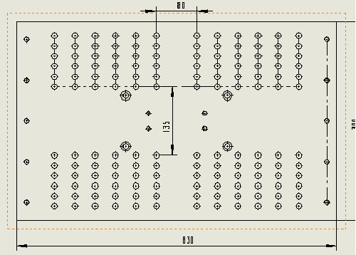
5.03 Max mold size: 640 × 550 mm.
Lower plate hole spacing: L570/400 × W520/420;
Upper plate hole spacing: L480/320 × W500/400/300/200.
1.4.5 Frame Structure
1. Upper frame: standard aluminum alloy; lower frame: 60 × 60 mm, 4 mm thick square tube welded and spray-coated.
2. All guard doors made of sheet metal (except feeding end). Upper doors have viewing windows. All doors equipped with sensors.
Sheet thickness ≥1.5 mm.
3. All solenoid valves/manifolds equipped with resin mufflers.
4. All pneumatic/electrical cable entries have noise-reduction treatment.
5. Noise at all equipment positions ≤80 dB.
1.4.6 Control Section
1. 65536-color true-color touchscreen.
2. HMI must be intuitive and easy to operate. Button size ensures no double pressing.
3. Operation panel must include: power ON/OFF, start, stop, and emergency stop (self-lock type).
4. All stations must have manual and single-station operation interfaces. Same station operations on same page.
5. Touchscreen displays Pocket forming and cutting cumulative and shift output. Resettable.
6. Upon fault, touchscreen must show complete alarm and self-diagnosis. Names must match those displayed.
7. In manual mode, motion units with logical relation must have reliable software interlock.
1.5 Major Components
1.5.1 Pneumatic: YSC
1.5.2 Switches/Electrical: CHINT
1.5.3 Sensors: Panasonic / OMRON / KEYENCE
1.5.4 PLC: Panasonic
1.5.5 HMI: Delta
1.5.6 Ball screw/linear guide: TBI / Dinghan
1.5.7 Motors/Drivers: Mitsubishi
1.5.8 Frame: welded square tube + coating (bottom), aluminum profile + transparent acrylic (top)
II. Compatible Incoming Material and Product Specifications
2.1 Incoming Material Dimensions
l Incoming material size specification: Ø350 × 550 mm
2.2 Maximum Formed Product Dimensions
l Maximum formed product dimensions: 560 mm (L, dual-pit) × 550 mm (including air bag W)
Code |
Name |
Specification |
A |
Case width (including airbag) |
60–550 mm |
B |
Body height |
≤280 mm |
J |
Top seal width |
2.5–25 mm |
2.3 Mold Configuration Compatibility
l The equipment is equipped with one set of integrated mold.
l Mold changeover time: 0.5–1 hour per person.
l Compatible with buyer's existing split-type mold.
III. Equipment Technical Parameters
Item |
Description |
Specification Requirement |
Equipment Function |
Yield |
First-pass yield: ≥99.5% (excluding defective incoming materials) |
Product Quality Requirement |
Servo system repetitive positioning accuracy: ±0.03 mm |
|
Trimming Accuracy Requirement |
±0.15 mm |
|
PPM |
≥5 PPM (one-out-one) (based on baseline cell model C5E2240) |
|
Machine Failure Rate |
≤1% |
|
Switching time |
≤1 hour/person (excluding mold debugging time) |
|
Incoming material compatibility |
Incoming material size specification: Ø350 × 550 mm |
|
Mechanical Section
|
Machine Overall Dimensions |
L 3200 mm × W 850 mm × H 1900 mm |
Machine Weight |
Load-to-area ratio < 500 kg/m² |
|
Main Component Selection |
Ball screw / linear guide: TBI / Dinghan |
|
Cutter mechanism standardized |
||
Consumables standardized |
||
Electrical Section
|
Input Voltage and Power |
Power 4.5 kW, using 3-phase 380V power supply |
Main Component Selection |
Pneumatic components: SMC / AirTAC (SMC preferred, AirTAC for non-critical use) |
|
Sensors: Daochuan / OMRON / KEYENCE |
||
Programmable logic controller: Panasonic |
||
Motor and driver: Mitsubishi |
||
Switches and electrical components: CHINT |
||
Touchscreen: Delta |
||
Electrical Wiring |
All wiring, air lines, and tubing must have clear labeling |
|
PLC must reserve at least 5 I/O ports, and reserve communication ports (Ethernet, RS232, etc.) |
||
Control System |
Provide PLC program source code and touchscreen program source code |
|
Provide relevant installation software as needed, such as driver software, industrial control cards, etc. |
IV. Equipment Installation Requirements
4.1 Equipment Power
Power: 4.5 kW, using three-phase AC 380V power supply.
4.2 Compressed Air
≥0.5 MPa, 20 L/min
4.3 Weight
Total weight (approximately): 800–1500 kg
Load-to-area ratio: ≤500 kg/m²
4.4 Environment Conditions
Room temperature: 10–40°C
Humidity: 30–70%, no condensation
No flammable or corrosive gases.
4.5 Structural Requirement
The overall equipment frame must be solid and movable by forklift.
4.6 Installation Location
Standard workshop


 +86 13174506016
 David@tmaxcn.com
 +86 18659217588
