 English▼


products categories
- Battery Production Equipment Line
- Battery Lab Pilot Equipment Line
- Lithium Battery Pack Assembly Line
- Solid State Battery Assembly Line
- Sodium Ion Battery Production Line
- Supercapacitor Assembly Line
- Lithium Ion Battery Recycling Plant
- Dry Electrode Preparation Solution
- Perovskite Based Solar Cell Lab Line
- Li ion Battery Materials
- Cathode Active Materials
- Anode Active Materials
- Customized Battery Electrode
- Coin Cell Parts
- Lithium Chip
- Cylindrical Cell Parts
- Battery Current Collectors
- Battery Conductive Materials
- Electrolyte
- Metal Mesh
- Battery Binder
- Separator and Tape
- Aluminum Laminate Film
- Nickel Strip
- Battery Tabs
- Graphene Materials
- Nickel Felt
- Titanium Fiber Felt
- Battery
- Battery Pack Machine & Compoments
- Battery Pack Compoments
- Turnkey Solutions Battery Pack Assembly Line
- Cell Sorter
- Battery Pack Spot Welder
- Laser Welder
- Battery Charging Discharging Tester
- Battery Pack Aging Machine
- Battery Pack Comprehensive Tester
- CCD Visual Inspector
- Battery Pape Sticking Machine
- BMS Testing Machine
- Al Wire Bonding Machine
- Lithium Battery Machine
- Battery Tester & Analyzer
- Battery Safety Tester
- Material Characterization Tester
- Rolling Press Machine
- Spot Welding Machine
- Vacuum Mixer Machine
- Crimping/Disassembling Machine
- Vacuum Sealing Machine
- Electrolyte Filling
- Stacking/Winding Machine
- Electrode Cutter/Slitter
- Pouch Forming Machine
- NMP Solvent Treatment System
- Lithium Battery Production Plant
- Vacuum Glove Box
- Furnaces
- Coaters
- PVD Coater
- Laboratory Press Machine
- Large Press Machine
- Planetary Centrifugal Mixer
- Ball Mill
- Laboratory Machine
- Cutting Machine
- Metal Foam
contact us
- If you have questions, please contact us, all questions will be answered
- WhatsApp : +86 18659217588
- Email : David@tmaxcn.com
- Email : Davidtmaxcn@gmail.com
- Add : No. 39, Xinchang Road, Xinyang, Haicang Dist., Xiamen, Fujian, China (Mainland)
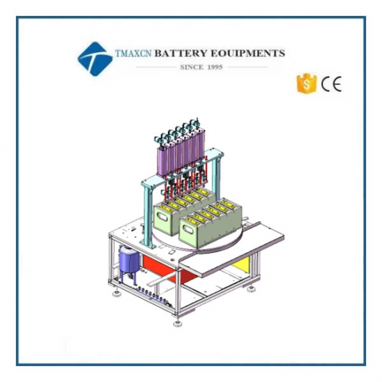
Automatic Prismatic Cell Electrolyte Filling Machine
Model Number:
TMAX-LKZYJ-06Compliance:
CE CertifiedWarranty:
2 Year Limited Warranty With Lifetime SupportPayment:
L/C D/A D/P T/T Western UnionDelivery Time:
5 days
- WhatsApp : +86 18659217588
- Email : David@tmaxcn.com
- Email : Davidtmaxcn@gmail.com
- Wechat : 18659217588
Previous:
Automatic Rotary Pouch Cell Electrolyte Filling MachineNext:
Rotary Semi-Automatic Prismatic Cell Electrolyte Filling Machine
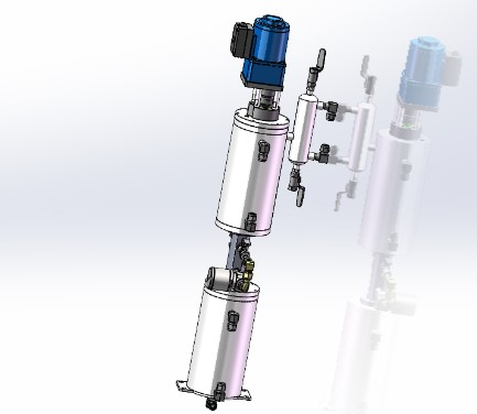
Automatic Prismatic Cell Electrolyte Filling Machine
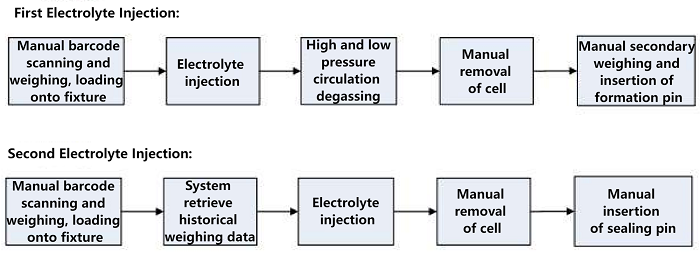
I. Equipment Function
1.1 The equipment is applicable for electrolyte filling of prismatic lithium-ion cells (aluminum-case), and is compatible with first filling and second filling.
1.2 The operator first performs manual barcode scanning and weighing on the unfilling cell, then places the cell into the fixture to carry out automatic electrolyte filling and high/low-pressure automatic circulation. Afterward, the operator removes the cell from the fixture, and after filling again performs barcode scanning and weighing.
1.3 Used inside the dry room.
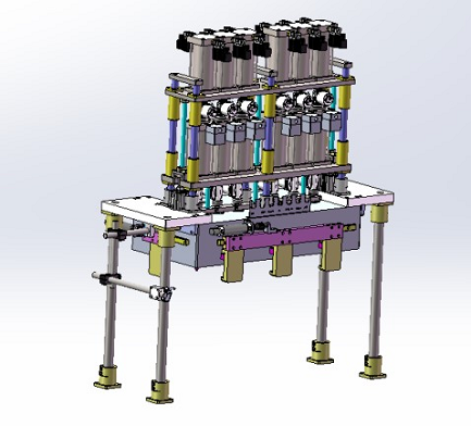
1.4 Process diagram:
II. Applicable Product Specifications:
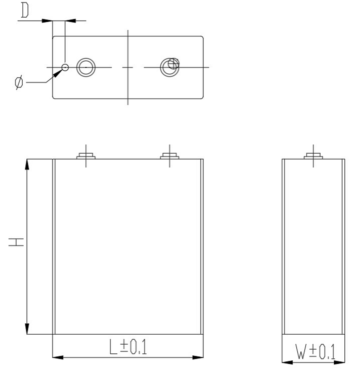
Cell Width |
Cell Height |
Cell Thickness |
Filling-hole Edge Distance |
Filling-hole Diameter |
80–180 mm |
80–210 mm |
25–75 mm |
≥ 5 mm |
1.2–2.0 mm |
III. Main Technical Parameters
No. |
Item |
Specification / Requirement |
1 |
Filling method |
Differential-pressure filling |
2 |
Equipment filling accuracy |
≤ 8‰ g |
3 |
Filling pump specification |
Electronic ceramic variable pump (single-stroke filling ≤ 15 g) – 1 unit |
4 |
Filling pump precision |
Single-stroke 15 g ± 0.05 g |
5 |
Degassing method |
Multiple degassing (vacuum + pressurization); maximum vacuum ≤ −0.09 MPa |
6 |
Degassing time |
1–99 s adjustable (Note: degassing + pressurization time directly affects efficiency) |
7 |
Electronic scale precision |
±0.1 g |
8 |
Electronic scale range |
8000 g |
9 |
Changeover time |
≤ 30 min for skilled operator |
10 |
Equipment utilization rate |
> 98% (excluding scheduled maintenance, preparation, material changeover) |
11 |
First-pass yield |
≥ 99.5% |
III. Introduction of Each Mechanism of the Equipment
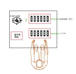
I. Equipment Layout Diagram
II. Basic Parameters
1. Power configuration: AC220V ±10% / 50 Hz
2. Power: 3 kW
3. Compressed air: pressure 0.5–0.7 MPa (5–7 kgf/cm²)
4. Compressed-air consumption: 10 L/s, dried, filtered, regulated
5. Vacuum source: ≤ −0.098 MPa, 20 L/s
6. Ambient dew point: < −50°C (dehumidifier provided by customer)
7. Load-bearing: installation floor load requirement > 500 kg/m²
8. Equipment weight: approx. 2.0 T
9. Overall dimensions: 1500 (L) × 1600 (W) × 2000 (H) mm (subject to actual)
IV. Equipment Functional Requirements
4.1 Scanning Module: one set
l Automatic scanning, information automatically transmitted to the host computer, for one-to-one binding of cell and filling volume;
l Scanner brand: domestic
l Handheld barcode scanner, manual scanning.
l Can scan barcodes and QR codes, both horizontal and vertical;
l For NG scans, automatic alarm, manual handling.
l Scanning success rate ≥ 99.9%.
4.2 Weighing Module: one set
l Electronic scale precision: 0.1 g; range 8000 g; calibration weight precision within ±0.005 g; difference between pre/post weighing within ±0.03 g
l Uses independent grounded stand, reasonable wiring, installed independently on a counterweight platform to avoid vibration; counterweight ≥ 20 kg
l Real-time single-machine communication detection function:
l Scanning and weighing data are automatically recorded into the host computer and one-to-one bound; after weighing, the data are bound and received/processed by the IPC and stored in the database; weighing data are output via Excel, with no data loss.
l The weighing value is bound with the cell barcode and uploaded to the buyer’s traceability system;
l Electronic scale brand: domestic, auto zero each time.
l Provide 50 g calibration weight for scale calibration, with a reserved position for the weight at the weighing station.
l The electronic scale is equipped with an anti-shock mechanism.
4.3 Electrolyte-Filling Fixture Mechanism: one set
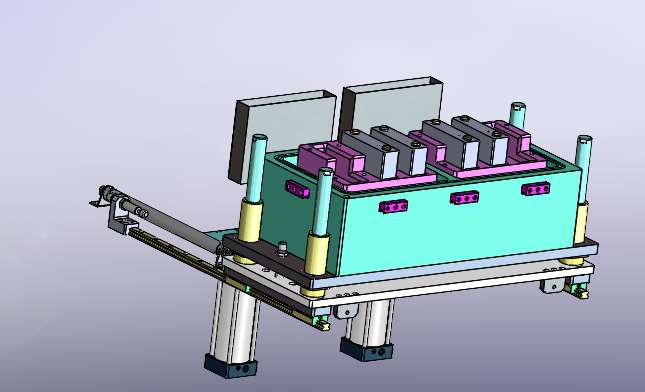
l The operator places the cell into the fixture (one-out-six fixture).
l Fixture positioning via positioning guide bushing. Simple changeover, no adjustment required.
l The vacuum gauge is corrosion-resistant.
4.4 Filling Mechanism: one set
l One filling cup ↔ one cell.
l Adjustable filling-amount parameters.
l Uses differential-pressure filling mode, −0.095–0.2 MPa.
l Six sets of filling cups, six sets of liquid reservoirs.
l Filling cups material SUS316; cup ≤ 750 g; inner arm roughness ≤ 0.4 μm.
l Alignment accuracy between filling port and filling nozzle ±0.5 mm.
l Adjustable filling amount 0–750 g, auto-adjustable per cell weight.
l Chamber pressure-holding test: under 0.8 MPa condition, system leakage rate ≤ 1.0 kPa/min.
l Automatically completes cell vacuuming and filling; vacuum ≤ −95 kPa, adjustable.
l Supports single-cell production.
l Equipped with one variable single-head filling pump.
l For second filling, the system shall have closed-loop control: based on pre/post weighing info, automatically adjust the filling-pump speed; interacts with the first-filling data to obtain pre-weighing info, ensuring total electrolyte retention remains constant.
l If the set vacuum/pressure cannot be reached during chamber vacuuming/pressurization, the system stops and alarms automatically.
l After power-off or air-loss shutdown, the chamber, vacuum pipeline, and pressurization pipeline shall self-lock.
l The electrolyte supply pipeline system shall adopt sealed design; the manifold shall adopt distributed design.
l Each independent pipeline is equipped with a valve body to switch vacuum / electrolyte.
l Each vacuum pipeline is equipped with a digital vacuum gauge, with range meeting −100 kPa detection.
l Vacuum pipes entering the chamber use SUS304 (food-grade, surface roughness ≤ 0.8 μm).
l A cone valve is installed below the filling cup to control switching between liquid and gas lines; the cup bottom is equipped with a quick-release filling nozzle.
l Filling nozzle design requirement: must seal to the step of the cell’s filling hole during filling.
l Filling nozzle material: EPDM; all static seals use O-rings, EPDM.
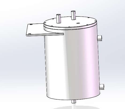
4.5 Electrolyte Tank Mechanism: one set
l The system includes electrolyte filtering, degassing, and storage.
l System hardware: filter, degassing tank (with agitator), storage tank, filling pump; all wetted materials SUS316; all tanks equipped with level sensors.
l A filter is installed before the degassing tank, filtration precision 1 μm.
l Storage tank and degassing tank use nitrogen pressurization (nitrogen supplied by Party A’s plant).
l Degassing tank and storage tank have 4 level high/low limit sensors (UU, UL, LU, LL); storage tank outlet has electrolyte mesh filter ≥ 100 mesh (pore ≤ 74 μm, SUS316).
l UU: if the inlet valve leaks or UL sensor fails, electrolyte keeps rising; reaching UU triggers alarm + stop.
l UL: during replenishment, reaching UL automatically stops liquid addition.
l LU: as electrolyte is consumed, reaching LU automatically replenishes.
l LL: if LU sensor fails, reaching LL triggers low-level alarm + stop.
l Filling pump placed close to storage tank to minimize pipeline length.
l Vacuum main line has an electrolyte filter to prevent electrolyte entering the vacuum pump.
l Degassing tank requires −90 kPa vacuum, hold 2 min.
l Tank volume 20 L.
l No bending allowed in any liquid pipeline.
l Filling amount set on touchscreen, automatic adjustment.
l Precision ceramic valve with reciprocating rotary motion.
l Static sealing parts: EPDM.
4.6 Residual-Liquid Recovery System: one set
l Residual-liquid collection tank material SUS304.
l Equipped with level sensor; automatic alarm when full.
4.7 Safety & Fire-Protection System: one set
l Equipment protective cover shall use flame-retardant materials.
l Equipment platform uses Q235 with surface chrome plating or aluminum plate, surface anodized, then overlaid with stainless-steel sheet-metal.
4.8 Control System
l Controlled by industrial PC and PLC; the sealing head is controlled by a temperature-control module to ensure the best one-pass result.
l The equipment is provided with communication interfaces with upstream/downstream machines and the central monitor (Ethernet) to facilitate remote monitoring and checking of machine status and parameter settings;
l Equipped with an IPC to read scanner data and pre/post filling weighing data, judge NG/OK filling amount, and store data in the computer.
l Data are uploaded to the MES according to the MES interface requirements.
l Local data storage: automatically exported to the designated directory per the set cycle; data stored by day in folders (same as data uploaded to MES) to form a local backup.
l If the MES network is interrupted or upload fails for other reasons, the software stores the failed-to-upload files on disk; after the interface is restored, it uploads automatically.
l Local data storage: automatically exported to the designated directory per the set cycle; data stored by day in folders.
l Reserved for future MES docking expansion. Party A to provide MES docking details. Upgrade the upper-computer data-acquisition software.
4.9 Machine Fixed Frame
l Uses welded square tubing, ensuring stable operation.
l Layout, operation, and maintenance conform to ergonomics, with sufficient space reserved for operation and maintenance.
l Machine-cover observation windows use transparent acrylic.
l Footings are reasonably distributed—overall at four corners, with local reinforcement where needed.
l Sufficient cooling fans are configured around the electrical cabinet; all fans have independent power; the cabinet has lighting, with the lighting circuit on an independent breaker.
l Internal cabling uses cable trays; the equipment is in a sealed environment, with transition chambers at loading/unloading positions. Dry-air inlet / exhaust port OD = 70 mm.
V. Main Composing Mechanisms and Functions of the Equipment
No. |
Mechanism Name |
Function |
Qty (set) |
1 |
Scanning mechanism |
Manual scanning of the cell |
1 |
2 |
Weighing mechanism |
Manual weighing of the cell |
1 |
3 |
Filling rotary-table mechanism |
Manual loading/unloading and pre-sealing for filling |
1 |
4 |
Electrolyte degassing system |
Reduce bubbles in the electrolyte to ensure filling accuracy |
1 |
5 |
Electrolyte filtering system |
Reduce contamination of the vacuum system by electrolyte |
1 |
6 |
Frame |
Welded square tubing |
1 |
VI. Main Component Configuration of the Equipment:
1. Cylinder / Solenoid valve / Manifold: SMC / CKD / Airtac
2. Pneumatic components: SMC / CKD / Airtac
3. Servo motor: OMRON / Mitsubishi / Panasonic / Inovance or equivalent brands
4. Bearings: THK / NSK
5. Guide rail / Ball screw: ABBA / HIWIN or equivalent brands
6. PLC: XINJE
7. Touchscreen: XINJE
8. Vacuum gauge: Domestic
9. Electronic scale: Domestic
10. Filling pump: Jiyanda
11. Barcode scanner: Domestic
12. Air tubing / fittings: corrosion-resistant air tubing; metal pneumatic fittings to resist electrolyte corrosion
13. IPC: Advantech / Yankong
VII. Delivery List
No. |
Name |
Specification/Model |
Qty of Wear Parts Supplied |
Manufacturer |
1 |
Filling nozzle |
P10BN |
4 pcs |
Sanxing Jiyan |
2 |
Vacuum tube |
1-inch steel-wire mesh hose |
2 m |
— |
3 |
Heating tube |
Φ8 × 200, 400 W |
2 pcs |
— |
4 |
Temperature-sensing wire |
A-100 K2M TEFLON 7/0.2 × 2 |
2 m |
Minyang |
5 |
Solid-state relay |
G3NA-210B (DC 5–24) |
2 pcs |
Omron |
6 |
Fuse |
10 A |
5 pcs |
Luko |
7 |
Hex wrench set |
1.5–10 mm |
1 set |
TGK |
8 |
Open-end wrench set |
6–22 mm |
1 set |
— |
9 |
Adjustable wrench |
— |
1 pc |
— |
10 |
Screwdrivers |
101 flathead, 101 Phillips |
1 each |
— |
11 |
Toolbox |
— |
1 pc |
— |


 +86 13174506016
 David@tmaxcn.com

