 English▼


products categories
- Battery Production Equipment Line
- Battery Lab Pilot Equipment Line
- Lithium Battery Pack Assembly Line
- Solid State Battery Assembly Line
- Sodium Ion Battery Production Line
- Supercapacitor Assembly Line
- Lithium Ion Battery Recycling Plant
- Dry Electrode Preparation Solution
- Perovskite Based Solar Cell Lab Line
- Li ion Battery Materials
- Cathode Active Materials
- Anode Active Materials
- Customized Battery Electrode
- Coin Cell Parts
- Lithium Chip
- Cylindrical Cell Parts
- Battery Current Collectors
- Battery Conductive Materials
- Electrolyte
- Metal Mesh
- Battery Binder
- Separator and Tape
- Aluminum Laminate Film
- Nickel Strip
- Battery Tabs
- Graphene Materials
- Nickel Felt
- Titanium Fiber Felt
- Battery
- Battery Pack Machine & Compoments
- Battery Pack Compoments
- Turnkey Solutions Battery Pack Assembly Line
- Cell Sorter
- Battery Pack Spot Welder
- Laser Welder
- Battery Charging Discharging Tester
- Battery Pack Aging Machine
- Battery Pack Comprehensive Tester
- CCD Visual Inspector
- Battery Pape Sticking Machine
- BMS Testing Machine
- Al Wire Bonding Machine
- Lithium Battery Machine
- Battery Tester & Analyzer
- Battery Safety Tester
- Material Characterization Tester
- Rolling Press Machine
- Spot Welding Machine
- Vacuum Mixer Machine
- Crimping/Disassembling Machine
- Vacuum Sealing Machine
- Electrolyte Filling
- Stacking/Winding Machine
- Electrode Cutter/Slitter
- Pouch Forming Machine
- NMP Solvent Treatment System
- Lithium Battery Production Plant
- Vacuum Glove Box
- Furnaces
- Coaters
- PVD Coater
- Laboratory Press Machine
- Large Press Machine
- Planetary Centrifugal Mixer
- Ball Mill
- Laboratory Machine
- Cutting Machine
- Metal Foam
contact us
- If you have questions, please contact us, all questions will be answered
- WhatsApp : +86 18659217588
- Email : David@tmaxcn.com
- Email : Davidtmaxcn@gmail.com
- Add : No. 39, Xinchang Road, Xinyang, Haicang Dist., Xiamen, Fujian, China (Mainland)
-
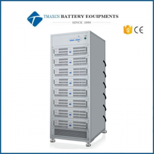
 30V 10A 8 Channel Battery Pack Charging and Discharging Machine
-
60V 10A 8 Channel Battery Pack Charging and Discharging Machine
-
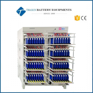
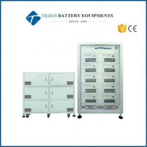
20V 30V 60V 10A 8 Channel Battery Pack Charging and Discharging Machine Aging Cabinet
-
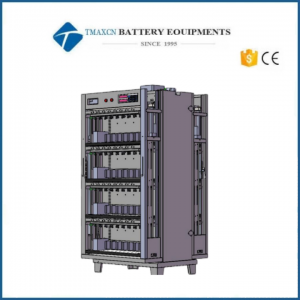
 5V 10A 192 Channel Prismatic Cell Tester Grading Machine
-
 200V 100A EV Battery Tester Lithium Battery Pack Aging Machine Tester
-
 100V 100A Lithium Battery Tester Grading Machine
-
 5V30A 16 Channel Prismatic Cell Formation Charging and Discharging Tester
MSK-180S is a gas driven die cutter for producing pouch battery cathode/anode electrodes ( no electricity required ) Its compact design enables the operation inside a glove box with Ar atmosphere where moisture/oxygen-sensitive electrodes will be cut
-
100V 100A EV Car Battery Lithium Battery Tester Grading Machine
-
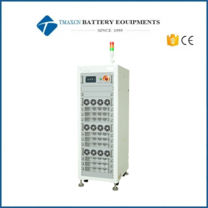
 120V 30A Regenerative Type Battery Pack Charge Discharge Aging Machine
-
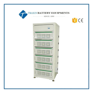
 100V 20A Charge Discharge Regenerative Type Battery Pack Aging Machine
-
 5V 30Ah 50Ah 60Ah 100Ah 8 16 32 64 Channel Prismatic Battery Tester with Regenarative Function
-
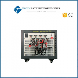
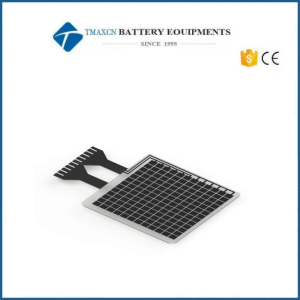 Lab Battery Pressure Distribution Tester Measure System For Lithium Battery R&D
Lab Battery Pressure Distribution Measure System For Lithium Battery R&D 1. Background As a common electric energy storage device, lithium-ion battery (LIB) has the advantages of high energy density, high specific power, high output voltage, small self-discharge, long service life, etc.which is widely used in electric vehicles, electronic products and other fields. On the one hand, during the manufacturing process of the LIB, the internal stress distribution or the surface thickness distribution will be uneven because the process environment cannot be completely consistent; On the other hand, in the electrochemical cycle process, intercalation and deintercalation of Li-ions will lead to the volume expansion and contraction. However, the uneven current density or temperature distribution inside the LIB, will lead to the uneven distribution of the stress during the expansion of the LIB. Thus, the quantitative characterization of the stress distribution on the surface of LIB can provide a deeper perspective for the battery stress analysis, assist technicians to analyze the battery stress distribution, explore the causes of the failure of the LIB, and develop a safer and more reliable LIB 2. Introduction of Pressure Distribution Measure System Software interface: Characteristic: 1. Display the resultant force curve of each detection unit in real time; 2. Select the pressure distribution diagram according to the user's actual used area; 3.Synchronize the charging and discharging data in real time; 4. One-click to export the data report; 5. Real-time calibration of pressure (combined with in-situ expansion equipment). 3. Applications Application 1: Test of stress distribution on the surface of the cell during the cycle Test information: NCM-Graphite system, 3~4.3V, 0.5C, 50kg preload; Result analysis: It can quantitatively characterize the difference of stress distribution on the surface of the cell, provide a deeper perspective for the stress analysis of the cell, and help technicians analyze the stress distribution in the cell, explore the causes of failure of the cell, and develop a safer and more reliable cell. Application 2: Surface flatness test of fresh cell Result analysis: there is a certain correlation between the cell process design and the cell pressure distribution (flatness). Technicians can develop appropriate distribution standards through the pressure distribution system to monitor the batch stability of the delivered cells. 4. Model and Specification Sensor film size 160*160mm(Can be customized according to customer needs) Pressure range of sensing unit 0~30kg(0~5MPa) Pressure accuracy of sensing unit ±10% FS Sensing unit size 7.5*7.5mm Sensor thickness <0.3mm Number of sensors 16X16 array layout, 256 sensors in total Data collector 1 (sampling frequency<10Hz), size about 20 * 80 * 120mm Software 1 set
-
 Laboratory Lithium-ion Battery Pouch Cell Electrode Resistance Testing Tester Machine
Battery Electrode Resistance Analyzer Machine for Lithium Battery Testing The importance of electrode resistance Electrode resistance (conductivity) influences the basic performance of batteries, not only on the power capability (internal resistance), but also on the reliability or safety performance. Through the measurement of electrode resistance the property of electric conductive, micro-structural uniformity of electrodes can be evaluated during die electrode many&manu&cture process in advance, thus help us to research and improve the formulation of composite electrodes as well as the control parameters of mixing, coating and calenderii^; processes. In the composite electrodes, the electric conductivity is determined by several primary factory, such as the inter&cial resistance between the coating layer and the conductive foil, the distributions of conductive agents, die intrixisic resistance of active material and the contact areas between particles. The functions of BER multi-function electrode resistance analysis method for electrode process monitoring are listed as follows: Comprehensively assessment of the slurry stability from the stirring, coating to the calendering process, which helps to recognize die anomaly aggregation of conductive agents in advance; Recognition of uneven mixing on mixture silicon—carbon cathode; Assessment of dectric conductivity offonnulas for diferent active materials; Assessment of electric conductivity of formulas for diferent conductive agents; Assessment of electric conductivity of the functional pre—coating lays of current collector; Failure analysis for the electric conductive networic failure of batteries; Analysis of contact resistance of the positive or negative electrode sur&ce after formation. The limitations of traditional test methods Currently, there are several methods have been used to test the electrode resistance, such as four point probe method or multi point probe method and single point probe method. Though these traditional methods may have been maturely used in di&rent types of film industry areas, for the evaluation of the composite electrode films in lithium ion batteries, there are still several deficiencies that can not be ignored. The four point probe film resistance test method has been wildly used in thin films industries, which use four or even more probes array to test the film resistance form film sur&ce. Its test procedure is easy and simple, and it can reveal the anisotropic resistance components of thin film by a simple equivalent circuit model fitting. However, considering its test principle and model fitting process, this mediod can only be suitable for a uniform thin film with smooth sur&ce, and the test sample should be loaded on an insulating substrate for ideal resistance fitting. Unfortunately, the electrodes ofliduum ion batteries are composite electrode with complex compositions, rough sur&ce and loadit^ on a low resistance current collector, so their four point probe test data, are often inconsistent and difficult to analyze the result by theoretical models. Increasing die probe number and using more complicate models can improve the test reliability to a certain extent, but that need more complex structures, and again the result analysis is still difficult. The single point test method was another wildly used method in the lithium ion batteries industry, which use a fixed probe on the end of the curtent collector and a mobile probe on the surface of the electrode to directly measure the electrode resistance. This is a very simple way of electrode resistance test often carry out by a homebuilt system for difierent users, but it is still a rough empirical test method without considering the influence of press pressure, conductive path length, substrate materul and so on. As a result, the single point probe method can not provide a reliable and consistent electrode resistance data as well. Methods Four point probe test Single point probe test Electric test circuit Kelvin four-wire test technology + direct current stimulation Kelvin four-wire test technology + alternating-current Probe structure four assembled equidistant probes (< ® 1mm), which's tops are kept in the same plane during the test to get a physical contact with the sample surface One probe (usually is an alligator clip) is fixed on the current collector, and the other probe (usually is a Cu terminals) is mobile to contact on the sample surface Applicable samples Single component thin layer material with smooth surface Composite electrode with current collector Advantages and limitations √ Simple and fast measurement √ To reveal the anisotropic resistance components of thin film X Not suitable for composite electrode with current collector √ Simple and fast measurement √ Suitable for composite electrode with current collector x X A rough empirical test method without considering the influence of press pressure, conductive path length, substrate material, etc. * Developed with CATL the top power battery company and Authorized exclusively for the Patent. The TMAX’s creative solution The BER series Battery electrode resistance analyzer uses the upper and lower plane controllable pressure probes to directly measure the electrode to obtain the overall resistance and resistivity in the thickness direction of the electrode, including the contact resistance between the probe and the coating, the coating resistance, and the contact resistance between the coating and the current collector. Current collector resistance; The BER series is the first Battery electrode resistance analyzer for the lithium battery industry . The dual—plane controllable—pressure high—conductivity probe designed for composite electrode diaphragms and micron—level flat surface treatment ensure measurement accuracy; the high-precision resistance resolution and the attached calibration module ensure stable and reliable measurement results. Introduction of principles Multi-function One — stop data collection of key parameters including pressure, film resistance, film thickness, temperature, humidity, etc.; guarantee the reliability and traceability of measurement result. Automatic measurement Automatic measurement of the resistance under different pressure, thickness, temperature and humidity, etc.; provide a real time data display. Professional processing software *Provides various resistance measurement and analysis methods, including Single point test, continuous test, *Fixed pressure mode, variable pressure mode (ForBER1300) Show data curve *Different presented modes of data analysis and statistics. Integrated design Complete integration of pressure control module, resistance and voltage measurement module, thickness measurement module and the chamber illuminating module Device Four-probe and multi-probe methods BER series Principle Kelvin four-wire method+DC excitation Kelvin four-wire method+AC excitation current Structure Four taper equidistant probes in the same Φ14 mm copper terminals located at the upper and lower Suitable Single-component film with smooth surface(non-battery electrode) Thick composite material(battery electrode) with resistance Features Measure single-component film resistance and conductivity or smooth surface Measure the resistance and conductivity of the battery electrode, adjustable test pressure Conclusion 1.The traditional test method does not consider the influence of parameters such as pressure and contact area during the electrode test, and the theoretical calculation model of the multi-probe is quite different from the actual sample, and the data results are uncontrollable; 2.The BRE series electrode resistance meter can accurately control the test parameters such as test pressure and area to ensure stable and reliable results, and can directly obtain the corresponding relationship between the electrode compaction and the electrode resistance. *Developed with CATL the top power battery company and Authorized exclusively for the Patent Software Measurement system analyze *Part of the data comes from the partners, and the copyright belongs to the relevant parties. It can not be reproduced or used without consent. Applications Material evaluation 1.Correlation between powder conductivity and electrode conductivity Results Analyze Adjust the Ni content in the NCM material, and test the powder conductivity. It can be found that as the Ni con tent increases, the powder conductivity increases; Comparing three NCM pieces with different Ni content, it can also be obtained that as the Ni content increases, the conductivity of the electrode piece increases; Powder resistivity and electrode have the same trend! 2.Evaluate the resistivity of uncalendered electrode pieces under different compaction densities Conditions: 5-60MPa, step 10MpPa, keep 25s Results Analyze ♦ For graphite electrode, with the increase of compaction density, the resistivity continues to decrease. The reason is that the contact between active materials increases, and the overall conductivity of the electrode becomes better; ♦ For NCM electrode, with the compaction density increases, the resistivity of the pole piece continues to decrease. The main reason is that as the pressure increases, the contact between terminals and the active material becomes better; Process evaluation 1.Evaluation of electrode primer technology <a> The thicker the primer, the greater the resistance of the current collector; <b> The thicker the primer, the greater the cathode resistance; <c> After determining the best primer coating process based on the correlation between the two, the electrode resistance test can be used as a method for long-term monitoring of process stability. 2.Conductive agent distribution uniformity evaluation By monitoring the change use the resistance of the battery electrode, an abnormal battery electrode can be quickly identified, to prevent the bad battery electrode from flowing into the next process, and to save production costs. Cell evaluation 1.Analysis of electrode resistance during high temperature cycle&storage *The resistance of the cathode continues to increase with the increase in the number of cycles, indicating that a large change has taken place on the cathode side after the high temperature cycle, which may be related to the byproducts on the surface of the cathode particles or the contact between the particles; *The resistance of the anode membrane increases with the storage time, which indicates that the anode side has changed a lot during the storage process, which may be related to the increase of side reactions on the anode material surface *Part of the data comes from the partners, and the copyright belongs to the relevant parties. It can not be reproduced or used without consent. Parameter Resistance range 1uΩ-3.1kΩ Resistance accuracy ±0.5%FS Pressure range 50-600kg/5-35MPa(BER2100/BER2200) 50-1000kg/5-60MPa(BER2300/BER2500) Pressure accuracy ±0.3%F.S Thickness range 0-5mm(BER2500) Thickness resolution/accuracy 0.1um/±1um(BER2500) Temperature and humidity 0-50℃, 20-90%RH Temperature and humidity accuracy ±2℃, ±5%RH Installation requirement voltage 200-240V/50-60Hz Voltage variation tolerance ±10% Power dissipation 50W(BER2100/BER2200)/450W(BER2300/BER2500) Air source Pipeline gas or air compressor is required(BER2100/BER2200) Environmental temperature 25±5℃ Environmental humidity Humidity <80%RH at the temperature of 40℃ Environmental magnetic field Keep away from intense electromagnetic Net weight 76kg(BER2100/BER2200), 83kg(BER2300), 85kg(BER2500) Dimension(W*D*H) 355*320*550 mm(BER2100/BER2200) 355*320*800(BER2300/BER2500) Note: TMAX is committed to continuous improvement of products. TMAX reserves the right to alter the specifications of its products of its products without notice. All trademarks are registered by TMAX. Model BER2100 BER2200 BER2300 BER2500 Press mode Cylinder(pipeline gas required, range: 5-35MPa) Servo motor(No pipeline gas required, range: 5-60MPa) Testable parameters Resistance, pressure Temperature and humidity Resistance, pressure Temperature and humidity conductivity, resistivity Resistance, pressure temperature and humidity conductivity, resistivity Resistance, pressure Temperature and humidity conductivity, resistivity thickness, compaction density Function One point test Constant pressure condition Included BER2100 function Automatic measurement software Included BER2200 function Variable pressure Included BER2300 function Thickness measurement Compaction density measurement
-
Lithium-ion Battery Electrode Resistance Tester Device For Cylindrical Cell Electrode Analyse
Lithium-ion Battery Electrode Resistance Tester Device For Cylindrical Cell Electrode Analyse The importance of electrode resistance Electrode resistance (conductivity) influences the basic performance of batteries, not only on the power capability (internal resistance), but also on the reliability or safety performance. Through the measurement of electrode resistance the property of electric conductive, micro-structural uniformity of electrodes can be evaluated during die electrode many&manu&cture process in advance, thus help us to research and improve the formulation of composite electrodes as well as the control parameters of mixing, coating and calenderii^; processes. In the composite electrodes, the electric conductivity is determined by several primary factory, such as the inter&cial resistance between the coating layer and the conductive foil, the distributions of conductive agents, die intrixisic resistance of active material and the contact areas between particles. The functions of BER multi-function electrode resistance analysis method for electrode process monitoring are listed as follows: Comprehensively assessment of the slurry stability from the stirring, coating to the calendering process, which helps to recognize die anomaly aggregation of conductive agents in advance; Recognition of uneven mixing on mixture silicon—carbon cathode; Assessment of dectric conductivity offonnulas for diferent active materials; Assessment of electric conductivity of formulas for diferent conductive agents; Assessment of electric conductivity of the functional pre—coating lays of current collector; Failure analysis for the electric conductive networic failure of batteries; Analysis of contact resistance of the positive or negative electrode sur&ce after formation. The limitations of traditional test methods Currently, there are several methods have been used to test the electrode resistance, such as four point probe method or multi point probe method and single point probe method. Though these traditional methods may have been maturely used in di&rent types of film industry areas, for the evaluation of the composite electrode films in lithium ion batteries, there are still several deficiencies that can not be ignored. The four point probe film resistance test method has been wildly used in thin films industries, which use four or even more probes array to test the film resistance form film sur&ce. Its test procedure is easy and simple, and it can reveal the anisotropic resistance components of thin film by a simple equivalent circuit model fitting. However, considering its test principle and model fitting process, this mediod can only be suitable for a uniform thin film with smooth sur&ce, and the test sample should be loaded on an insulating substrate for ideal resistance fitting. Unfortunately, the electrodes ofliduum ion batteries are composite electrode with complex compositions, rough sur&ce and loadit^ on a low resistance current collector, so their four point probe test data, are often inconsistent and difficult to analyze the result by theoretical models. Increasing die probe number and using more complicate models can improve the test reliability to a certain extent, but that need more complex structures, and again the result analysis is still difficult. The single point test method was another wildly used method in the lithium ion batteries industry, which use a fixed probe on the end of the curtent collector and a mobile probe on the surface of the electrode to directly measure the electrode resistance. This is a very simple way of electrode resistance test often carry out by a homebuilt system for difierent users, but it is still a rough empirical test method without considering the influence of press pressure, conductive path length, substrate materul and so on. As a result, the single point probe method can not provide a reliable and consistent electrode resistance data as well. Methods Four point probe test Single point probe test Electric test circuit Kelvin four-wire test technology + direct current stimulation Kelvin four-wire test technology + alternating-current Probe structure four assembled equidistant probes (< ® 1mm), which's tops are kept in the same plane during the test to get a physical contact with the sample surface One probe (usually is an alligator clip) is fixed on the current collector, and the other probe (usually is a Cu terminals) is mobile to contact on the sample surface Applicable samples Single component thin layer material with smooth surface Composite electrode with current collector Advantages and limitations √ Simple and fast measurement √ To reveal the anisotropic resistance components of thin film X Not suitable for composite electrode with current collector √ Simple and fast measurement √ Suitable for composite electrode with current collector x X A rough empirical test method without considering the influence of press pressure, conductive path length, substrate material, etc. * Developed with CATL the top power battery company and Authorized exclusively for the Patent. The TMAX’s creative solution The BER series Battery electrode resistance analyzer uses the upper and lower plane controllable pressure probes to directly measure the electrode to obtain the overall resistance and resistivity in the thickness direction of the electrode, including the contact resistance between the probe and the coating, the coating resistance, and the contact resistance between the coating and the current collector. Current collector resistance; The BER series is the first Battery electrode resistance analyzer for the lithium battery industry . The dual—plane controllable—pressure high—conductivity probe designed for composite electrode diaphragms and micron—level flat surface treatment ensure measurement accuracy; the high-precision resistance resolution and the attached calibration module ensure stable and reliable measurement results. Introduction of principles Multi-function One — stop data collection of key parameters including pressure, film resistance, film thickness, temperature, humidity, etc.; guarantee the reliability and traceability of measurement result. Automatic measurement Automatic measurement of the resistance under different pressure, thickness, temperature and humidity, etc.; provide a real time data display. Professional processing software *Provides various resistance measurement and analysis methods, including Single point test, continuous test, *Fixed pressure mode, variable pressure mode (ForBER1300) Show data curve *Different presented modes of data analysis and statistics. Integrated design Complete integration of pressure control module, resistance and voltage measurement module, thickness measurement module and the chamber illuminating module Device Four-probe and multi-probe methods BER series Principle Kelvin four-wire method+DC excitation Kelvin four-wire method+AC excitation current Structure Four taper equidistant probes in the same Φ14 mm copper terminals located at the upper and lower Suitable Single-component film with smooth surface(non-battery electrode) Thick composite material(battery electrode) with resistance Features Measure single-component film resistance and conductivity or smooth surface Measure the resistance and conductivity of the battery electrode, adjustable test pressure Conclusion 1.The traditional test method does not consider the influence of parameters such as pressure and contact area during the electrode test, and the theoretical calculation model of the multi-probe is quite different from the actual sample, and the data results are uncontrollable; 2.The BRE series electrode resistance meter can accurately control the test parameters such as test pressure and area to ensure stable and reliable results, and can directly obtain the corresponding relationship between the electrode compaction and the electrode resistance. *Developed with CATL the top power battery company and Authorized exclusively for the Patent Software Measurement system analyze *Part of the data comes from the partners, and the copyright belongs to the relevant parties. It can not be reproduced or used without consent. Applications Material evaluation 1.Correlation between powder conductivity and electrode conductivity Results Analyze Adjust the Ni content in the NCM material, and test the powder conductivity. It can be found that as the Ni con tent increases, the powder conductivity increases; Comparing three NCM pieces with different Ni content, it can also be obtained that as the Ni content increases, the conductivity of the electrode piece increases; Powder resistivity and electrode have the same trend! 2.Evaluate the resistivity of uncalendered electrode pieces under different compaction densities Conditions: 5-60MPa, step 10MpPa, keep 25s Results Analyze ♦ For graphite electrode, with the increase of compaction density, the resistivity continues to decrease. The reason is that the contact between active materials increases, and the overall conductivity of the electrode becomes better; ♦ For NCM electrode, with the compaction density increases, the resistivity of the pole piece continues to decrease. The main reason is that as the pressure increases, the contact between terminals and the active material becomes better; Process evaluation 1.Evaluation of electrode primer technology <a> The thicker the primer, the greater the resistance of the current collector; <b> The thicker the primer, the greater the cathode resistance; <c> After determining the best primer coating process based on the correlation between the two, the electrode resistance test can be used as a method for long-term monitoring of process stability. 2.Conductive agent distribution uniformity evaluation By monitoring the change use the resistance of the battery electrode, an abnormal battery electrode can be quickly identified, to prevent the bad battery electrode from flowing into the next process, and to save production costs. Cell evaluation 1.Analysis of electrode resistance during high temperature cycle&storage *The resistance of the cathode continues to increase with the increase in the number of cycles, indicating that a large change has taken place on the cathode side after the high temperature cycle, which may be related to the byproducts on the surface of the cathode particles or the contact between the particles; *The resistance of the anode membrane increases with the storage time, which indicates that the anode side has changed a lot during the storage process, which may be related to the increase of side reactions on the anode material surface *Part of the data comes from the partners, and the copyright belongs to the relevant parties. It can not be reproduced or used without consent. Parameter Resistance range 1uΩ-3.1kΩ Resistance accuracy ±0.5%FS Pressure range 50-600kg/5-35MPa(BER2100/BER2200) 50-1000kg/5-60MPa(BER2300/BER2500) Pressure accuracy ±0.3%F.S Thickness range 0-5mm(BER2500) Thickness resolution/accuracy 0.1um/±1um(BER2500) Temperature and humidity 0-50℃, 20-90%RH Temperature and humidity accuracy ±2℃, ±5%RH Installation requirement voltage 200-240V/50-60Hz Voltage variation tolerance ±10% Power dissipation 50W(BER2100/BER2200)/450W(BER2300/BER2500) Air source Pipeline gas or air compressor is required(BER2100/BER2200) Environmental temperature 25±5℃ Environmental humidity Humidity <80%RH at the temperature of 40℃ Environmental magnetic field Keep away from intense electromagnetic Net weight 76kg(BER2100/BER2200), 83kg(BER2300), 85kg(BER2500) Dimension(W*D*H) 355*320*550 mm(BER2100/BER2200) 355*320*800(BER2300/BER2500) Note: TMAX is committed to continuous improvement of products. TMAX reserves the right to alter the specifications of its products of its products without notice. All trademarks are registered by TMAX. Model BER2100 BER2200 BER2300 BER2500 Press mode Cylinder(pipeline gas required, range: 5-35MPa) Servo motor(No pipeline gas required, range: 5-60MPa) Testable parameters Resistance, pressure Temperature and humidity Resistance, pressure Temperature and humidity conductivity, resistivity Resistance, pressure temperature and humidity conductivity, resistivity Resistance, pressure Temperature and humidity conductivity, resistivity thickness, compaction density Function One point test Constant pressure condition Included BER2100 function Automatic measurement software Included BER2200 function Variable pressure Included BER2300 function Thickness measurement Compaction density measurement
-
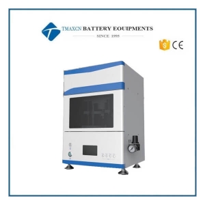
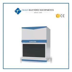 Lab Lithium-ion Battery In-Situ Gassing Volume Tester for Battery R&D
Lab Lithium-ion Battery In-Situ Gassing Volume Tester for Battery R&D Lithium-ion battery gassing behaviors Formation gas production: The formation process of lithium-ion batteries is accompanied by a large amount of gas production, which is closely related to the cell chemical system, anode and cathode materials, electrolyte components, and formation conditions; The formation conditions (such as current, cut-off voltage, temperature, pressure, etc.) affects the time of the formation step. Effectively shortening the formation cycle can greatly improve the production efficiency of the enterprise’s battery; At present, enterprises basically rely on empirical judgment for the setting of the formation process and conditions, and lack scientific and effective means and basis to improve the formation conditions; Gas production during overcharge: The risk of overcharge is a very important safety issue in actual use of lithium-ion batteries; Lithium-ion batteries will have serious side reactions during the overcharging process, and they are often accompanied by a large amount of gas generation, which makes the volume or internal pressure of the battery increase rapidly, increasing the risk of thermal runaway; Gas production during storage or cycle: During long-term storage or cycling, lithium-ion batteries will slowly undergo side reactions and produce gas, especially under high temperature conditions, which are more likely to occur. This is a very critical reliability issue for lithium-ion batteries. Functions of in-situ gassing volume analyzer GVM series In-Situ Gas Volume Analyzer adopts high accuracy mechanical monitoring system, which can in-situ record cells’ volume changes in the whole charge-discharge process, and obtain cells' accurate gassing volume and volume change rate during each stage. *Efficiency improvement: Rapidly evaluate the gassing behavior of cells, shorten R&D period, and improve efficiency; *Cost down:Help optimize formation process, improve production efficiency and decrease enterprise’s production cost; *Cell Design Optimization: Quantify the gassing volume and gassing rate during the cells1 whole formation process. By combining with the three-electrode analysis of formation curve, the systemic evaluation on the influences of different design factors on cells formation can be implemented, and help to optimize the cell performance by improving the SEI formation. *Reliability & Safety Design: In Situ gas volume monitor can also study and analyze the gassing behavior during the abuse test of overcharge, high temperature cycles and so on. Traditional test method Ex-Situ Volume Measurement: The method of displacement volume has been widely used to measure cells' volume after gassing. It is easy to operate but only provide limited information: *Single point measuring: unable to acquire the of volume change and gassing rate of the cells9 whole formation process; *Non-in-situ measuring: easy to be interfered, by external environment during the transfer-measurement process; *Weighed by General balance: unable to achieve an online, long-term, stable, and high-accuracy measurement. *High waste Of cells: unable to remove the influence of cell consistency. Internal Pressure Measurement The Internal Pressure Measurement is another widely used method, which monitor the internal pressure change of cells by implanting a pressure senor device into the cell. This method can be only applied on the prismatic cells, and need to prepare special cell sample, thus is complicated on operation and high cost consuming. Creative solution ln-situ measurement: With a self-developed high—accuracy mechanical sensing system installed in GVM series in situ gas volume monitor, we can implement a continuously long-term & high—stability measurement of Lithium Ion Batteries gassing process; High accuracy ADC data acquisition module is applied, and coordinated with multi-functional in situ gas volume monitor software MISG. The volume changes during the charge—discharge process of lithium ion battery can be monitored in real-time, and present the swelling and shrinkage level of battery online. Through CAN based communication data, it* s convenient to implement multi—module swelling. GVM series are the first in-situ gas volume monitors in lithium Ion battery Industry. *Developed with CATL the top power battery company and authorized exclusively for the patent. Device constitutional diagram and software High-energy learning test system: long-term in-situ online monitoring, and meet the accuracy requirements; Dedicated test software: real-time collection and display of mechanical test system data, and automatically draw volume change curves; Auxiliary system: special structure design, convenient to intervene in supporting auxiliary system, realize test temperature adjustment control. Applications Formation-gassing analyze 1.Different materials’ formation-gassing application Test condition: 25℃ 0.04C/0.1C The modified material A has a smaller particle size than the conventional material B, and the SEI film formation reaction is more sufficient during formation, and the gas production is larger; With the same design parameters, only the modification and surface modification of the material are performed. By comparing the gas production and gas production rate of the cell formation, the effect of the processed material on the cell formation can be quickly and intuitively obtained, helping the development and improvement of new materials. 2.Different electrolyte’s formation-gassing application(test condition: 25℃ 0.02℃) In the same electrolyte, the cell formation gas production and gas production rate of electrolyte B with a certain additive are greater than those of electrolyte A without additives. This additive can make the cell film forming reaction more complete; The additives in the electrolyte have a great influence on the SEI film formation reaction of the cell formation stage. By comparing the changes in the gas production volume and gas production rate of the cell formation by the electrolyte with different additives, the effect of the additive on the cell formation is quickly evaluated. The influence of the formation process, combined with the three-electrode formation curve, helps to improve the electrolyte formulation in a targeted manner. 3.Different temperature and rate of formation conditions Formation under different temperature In the same formation process, SEI filming reaction is more adequate at high temperature of 45deqC compared to that of 25degC. Formation under different charge rate At the same temperature^ with different formation rate, the reaction starting point of formation voltage is lower in smaller rate. The setting of the cell formation condition parameters affects the cell formation time and film quality. Effectively shortening the cell formation time can greatly improve the cell production efficiency of the enterprise. By setting parameters of different formation conditions, the starting point of the gas production voltage of the cell under different formation conditions and the gas production and gas production rate at each stage of the formation are obtained quantitatively, which helps guide the improvement of the cell formation process and technology, and improves the production efficiency of the enterprise . Overcharge-gassing analyze 1.Different NCM materials’ overcharge-gassing application(test condition: 25℃ 0.5℃) Comparing the cell SOC during gas production, it can be found that the high nickel cell produces gas earlier; By monitoring the normal charging process of the battery cell and the volume and temperature changes of overcharged to 200% SOC, and corresponding to the three-electrode curve, the potential and reaction rate of a large number of side reactions, the overcharged lithium potential, and the positive electrode material decomposition potential can be accurately obtained And rate and other related information, quantitatively help analyze and study the overcharge performance of materials, make targeted improvements, and improve R&D efficiency. 2.Different NCM materials’ overcharge-gassing application(test condition: 25℃ 0.5℃) *In the normal voltage range, the volume change of the cell is less than 1.2%, which is basically due to the structural swelling caused by lithium intercalation. When the SOC of high Ni-2 is greater than 40%, the structural swelling of high Ni-1 is slightly greater than that of high Ni-2; *After overcharging to 5V, the SOC of high Ni-2 material is later than that of high Ni-1 material, which indicates that high Ni-2 material can adapt to higher charging voltage, release more capacity and improve the energy density of the cell while maintaining stable structure; *The SOC and voltage of the cell corresponding to the starting point of gas production can be obtained by using the in-situ method to continuously monitor the overcharge gas production behavior; which is conducive to the development of the next step of R&.D work 3.Types and contents of electrolyte additives Comparing the overcharge gassing behavior of lithium-ion cell with two different types and contents of additives, it can be found that the reaction potential of additive-A is lower than that of additive-B, and the total gassing is lower a little more, it can be better used as overcharge protection additive. Cycle-gassing analyze Different NCM materials’ overcharge-gassing application(test condition: 60℃ 0.5℃ 3-4.2V) *Cell A and Cell B were used different ternary materials, the cell volume of cell-B increased more than that of cell A, and the irreversible volume increased from 0.01 ml to 0.04 ml; *Quantitative analysis helps to analyze the cycle performance of different materials, improving the efficiency of research and development. Storage-gassing analyze 1.Comparing NCM811 modified conditions Test condition: 4.2V full charge at 85℃ for 4H The results show that the voltage drop of NCM811 in modified method-1 is larger than that in modified mothod-2 at 85 °C, and the gas production is more ; The in-situ method can be used to continuously monitor the storage gas production behavior; which can compare the advantages of different modification methods of materials, improving the efficiency of research and development. 2.Comparing different type of electrode Test condition: 4.2V full charge at 85℃ for 4H *A and B of cells adopt different electrolyte systems. From the cell volume change curve during full charge storage, it can be seen that EL-A cells produce more gas than EL-B cells, which indicates that the electrolyte of system is easy to produce gas under high temperature and high pressure; *Quantitative analysis can help to study the gas production performance of different electrolytes, and improving the efficiency of research and development. 3.Comparing different storage temperature Test condition: 4.2V full charge at 85℃ for 4H The cell has good storage performance at 70 °C and high gas production at 85 °C ; By using in situ method to continuously monitor the storage gas production behavior, the starting point and maximum point of gas production can be obtained, which is helpful for the R & D personnel to carry out the next step of R & D work. Parameter and installation requirement Parameters 1.Total weight of pouch cell to be tested: IO-IOOOg, maximum size(excluding tabs, as shown on the below): 180*120 mm 2.Cell test temperature: 20-85℃ 3.Resolution of volume change: <1pL 4.Detection accuracy of volume change: <1OpL 5.System stability <20pL(RT25℃, <30min), <50uL(RT25℃, 30min-12h) Installation requirements of host device Desk Balance table Battery soaking liquid Mineral oil(like silicone oil) Voltage 200-240V/50-60Hz Voltage variation tolerance ±10% Power dissipation 150W(GVM2100), 280W(GVM2200) Environment temperature 25±5℃ Environmental humidity Humidity<95%RH at the temperature of 40℃ Environmental magnetic field Keep away from intense electromagnetic fields Net weight 55kg(GVM2100), 60kg(GVM2200) Dimension 500*500*700 mm Auxiliary device Charge-discharge device Self-supply or provided by supplier Computer Self-supply or provided by supplier Model GVM2100 GVM2200 Number of channels Single channel(one pouch cell) Dual channel(two pouch cells)
 +86 13174506016
 David@tmaxcn.com

