 English▼


products categories
- Battery Production Equipment Line
- Battery Lab Pilot Equipment Line
- Lithium Battery Pack Assembly Line
- Solid State Battery Assembly Line
- Sodium Ion Battery Production Line
- Supercapacitor Assembly Line
- Lithium Ion Battery Recycling Plant
- Dry Electrode Preparation Solution
- Perovskite Based Solar Cell Lab Line
- Electrode Preparation
- Li ion Battery Materials
- Cathode Active Materials
- Anode Active Materials
- Customized Battery Electrode
- Coin Cell Parts
- Lithium Chip
- Cylindrical Cell Parts
- Battery Current Collectors
- Battery Conductive Materials
- Electrolyte
- Metal Mesh
- Battery Binder
- Separator and Tape
- Aluminum Laminate Film
- Nickel Strip
- Battery Tabs
- Graphene Materials
- Nickel Felt
- Titanium Fiber Felt
- Battery Pack Machine & Compoments
- Battery Pack Compoments
- Turnkey Solutions Battery Pack Assembly Line
- Cell Sorter
- Battery Pack Spot Welder
- Laser Welder
- Battery Charging Discharging Tester
- Battery Pack Aging Machine
- Battery Pack Comprehensive Tester
- CCD Visual Inspector
- Battery Pape Sticking Machine
- BMS Testing Machine
- Al Wire Bonding Machine
- Lithium Battery Machine
- Battery Tester & Analyzer
- Battery Safety Tester
- Material Characterization Tester
- Rolling Press Machine
- Spot Welding Machine
- Vacuum Mixer Machine
- Crimping/Disassembling Machine
- Vacuum Sealing Machine
- Electrolyte Filling
- Stacking/Winding Machine
- Electrode Cutter/Slitter
- Pouch Forming Machine
- NMP Solvent Treatment System
- Lithium Battery Production Plant
- Vacuum Glove Box
- Furnaces
- Laboratory Press Machine
- Large Press Machine
- Coaters
- PVD Coater
- Ultrasonic Spray Coater
- Ball Mill
- Planetary Centrifugal Mixer
- Laboratory Machine
- Metal Foam
contact us
- If you have questions, please contact us, all questions will be answered
- WhatsApp : +86 18659217588
- Email : David@tmaxcn.com
- Email : Davidtmaxcn@gmail.com
- Add : No. 39, Xinchang Road, Xinyang, Haicang Dist., Xiamen, Fujian, China (Mainland)
Automatic Four-Station Pouch Cell Electrolyte Filling Machine
Model Number:
TMAX-ZYJ2Compliance:
CE CertifiedWarranty:
2 Year Limited Warranty With Lifetime SupportPayment:
L/C D/A D/P T/T Western UnionDelivery Time:
5 days
- WhatsApp : +86 18659217588
- Email : David@tmaxcn.com
- Email : Davidtmaxcn@gmail.com
- Wechat : 18659217588
Previous:
Automatic Pouch Cell Electrolyte Filling MachineNext:
Automatic Pouch Cell Rotary-Table Electrolyte Filling Machine
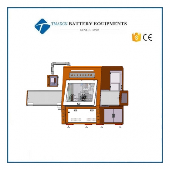
Automatic Four-Station Pouch Cell Electrolyte Filling Machine
1. Equipment Functions
Mainly used for automatic atmospheric-pressure electrolyte filling, vacuum degassing, and vacuum sealing of pouch lithium-ion cells. Realizes manual loading, automatic filling, automatic vacuum degassing, automatic sealing, and manual collection of pouch cells.
2. Applicable Product Specifications
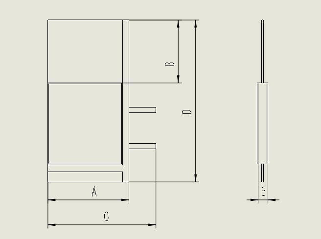
l A. Cell length: 40–180 mm
l B. Gas-bag width: ≥ 32 mm
l C. Total cell length: < 200 mm
l D. Total cell width: 70–120 mm
l E. Cell thickness: 2–15 mm
3. Main Technical Parameters
No. |
Item |
Specification |
1 |
Filling method |
Atmospheric-pressure filling |
2 |
Filling accuracy |
±1% |
3 |
Sealing-head pressure |
0.1–1.0 MPa, minimum adjustment resolution 0.1 MPa |
4 |
Degassing time |
0.5–99 s adjustable, accuracy ±0.2 s |
5 |
Sealing-head temperature |
Room temp–250 °C adjustable, control accuracy ±5 °C |
6 |
Heating rate of sealing head |
RT → 200 °C < 15 min |
7 |
Sealing result |
Surface free of bubbles, good tightness |
8 |
First-pass yield |
99% (excluding incoming-material defects) |
9 |
Equipment utilization |
95% |
10 |
Equipment efficiency |
≈ 2–8 ppm/m (depends on cell process) |
4. Equipment Features
1. Low failure rate and fast changeover (auto-adjustable filling pump reduces tuning time; optimized fixtures—only two screws to switch model).
2. Easy routine maintenance and quick PTFE (Teflon) tape replacement; higher productivity.
3. One-to-four ceramic metering pump with high accuracy; set fill mass on the HMI; greatly shortens tuning/changeover; anti-jam pump design.
4. Fixture 1-out-2 working mode; supports atmospheric filling, vacuum degassing, vacuum sealing.
5. All chambers use mechanical mechanisms for actuation—simplifies structural/electrical/pneumatic layout maintenance and speeds troubleshooting.
6. Dedicated electrolyte tank supports vacuum degassing in-tank, greatly reducing bubbles and contamination of the vacuum system.
7. Pneumatic components, electrical parts, and the electrical cabinet are isolated to avoid electrolyte contamination.
8. Adaptable to various cell sizes; simple adjustments—mainly fixture and fill mass.
9. Left/right sealing heads are cylinder-driven and guided by linear rails; smooth travel, accurate guidance, and flat seals.
10. Sealing heads made of copper for excellent heat transfer.
11. Left/right sealing-head pressure adjustable via regulators to meet different process requirements.
12. Left/right sealing-head temperature set on the temperature controller; PV/SV values displayed for intuitive operation.
13. Alarms for temperature abnormality, air-pressure abnormality, reset, etc.; machine only runs after reaching set temperature & pressure; buzzer prompt.
14. Pressure gauges with digital display and manual regulators for easy pressure setting.
15. Auto / semi-auto / manual modes; interlocked memory between auto and semi-auto.
16. EPDM sealing strips used for vacuum seals to resist electrolyte and extend life.
17. Swivel casters on lower frame for easy relocation.
18. For quality, all vent-in air for vacuum-chamber backfill must be dry gas from the machine.
19. Due to the complexity of pump control and machine control, an independent electrical cabinet is designed for easy maintenance.
20. Belt-type loading reduces labor, raises efficiency, and lightens operator workload.
5. System Protection Functions
1. Temperature controller provides over-temperature alarm to protect machine and cells.
2. Whether in auto or manual, all units with precedence logic are reliably interlocked to prevent mis-operation and hazards.
3. Anti-mis-step foot switch prevents unintended actuation.
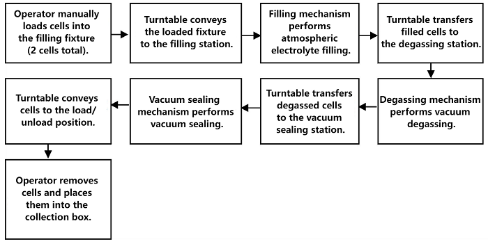
6. Equipment Functions and Operating Process
1. Supports the following sequence: Manual loading → Automatic filling → Automatic degassing → Automatic vacuum sealing → Manual unloading.
2. Electric pump connects automatically via an intermediate electrolyte buffer tank to two electrolyte tanks (with newly added degassing function).
3. Production action flow schematic diagram
7. Main Component Configuration
1. Cylinders / Solenoid valves / Manifolds: Airtac / Torque (Niuli De).
2. Bearings: THK / NSK / Taiwan brands.
3. PLC: OMRON / Mitsubishi.
4. Touchscreen: WEINVIEW (Weinview/Beijer “步科”).
5. Temperature controller: Yatai.
6. Vacuum gauge: NNT / Delta / Airtac.
7. Filling pump: Domestic electric pump.
8. Air tubing / fittings: Corrosion-resistant tubing, metal fittings.
9. Frame: Upper & lower frames welded from 40×40 square tube with sheet-metal welding.
10. Provide list of consumables and proprietary parts, and special maintenance tools.
11. Fixtures configured per the accepted cell model; when models change, fixture height can be adjusted. Additional fixtures will be quoted separately.
12. Provide the following documents with the machine: User Manual, Electrical Schematic, Electrical Wiring Diagram, Key Component Manuals, Consumables List, Certificate of Conformity.
8. Equipment Specifications and Installation Conditions
1) Technical parameters
l Filling accuracy: ±1%.
l Filling pump: 1-out-2, electronically adjustable fill mass.
2) Installation conditions
1. Power: AC 220 V ±10%, 50/60 Hz, 5 kW (by user).
2. Compressed air: ≥ 0.6 MPa, 0.5 L/s (by user).
3. Vacuum source: ≥ −0.09 MPa, 2 L/s (by user).
4. Ambient temperature: 20–50 °C; Relative humidity: 0–2% RH (dehumidification by user).
5. Coating color: Frame with baked-paint finish.
6. Installation environment: General room.
7. Total weight: ≈ 600 kg.
8. Machine size: L × W × H ≈ 1620 × 1400 × 1800 mm (excluding transfer window size).
9. Transfer-chamber size: Front L × W × H ≈ 1320 × 540 × 450 mm; Rear L × W × H ≈ 710 × 540 × 450 mm.
10. Overall size: L × W × H ≈ 3640 × 1480 × 1800 mm.
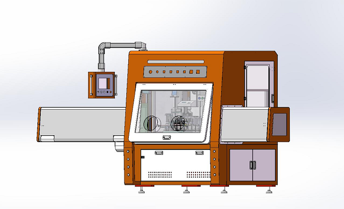
9. Equipment Diagrams
(Discharge transfer chamber)
(Filling machine structural diagram — for reference only; subject to the actual machine)
10. Spare Parts Supplied with the Machine
No. |
Name |
Model |
Qty |
1 |
Heating tube |
Ø10 mm × 305 mm |
2 pcs |
2 |
Sealing strip |
8 mm |
5 m |
3 |
Circuit diagrams |
— |
1 set |
4 |
Suction cups |
15 mm |
8 pcs |


 +86 13174506016
 David@tmaxcn.com

