 English▼


products categories
- Battery Production Equipment Line
- Battery Lab Pilot Equipment Line
- Lithium Battery Pack Assembly Line
- Solid State Battery Assembly Line
- Sodium Ion Battery Production Line
- Supercapacitor Assembly Line
- Lithium Ion Battery Recycling Plant
- Dry Electrode Preparation Solution
- Perovskite Based Solar Cell Lab Line
- Li ion Battery Materials
- Cathode Active Materials
- Anode Active Materials
- Customized Battery Electrode
- Coin Cell Parts
- Lithium Chip
- Cylindrical Cell Parts
- Battery Current Collectors
- Battery Conductive Materials
- Electrolyte
- Metal Mesh
- Battery Binder
- Separator and Tape
- Aluminum Laminate Film
- Nickel Strip
- Battery Tabs
- Graphene Materials
- Nickel Felt
- Titanium Fiber Felt
- Battery
- Battery Pack Machine & Compoments
- Battery Pack Compoments
- Turnkey Solutions Battery Pack Assembly Line
- Cell Sorter
- Battery Pack Spot Welder
- Laser Welder
- Battery Charging Discharging Tester
- Battery Pack Aging Machine
- Battery Pack Comprehensive Tester
- CCD Visual Inspector
- Battery Pape Sticking Machine
- BMS Testing Machine
- Al Wire Bonding Machine
- Lithium Battery Machine
- Battery Tester & Analyzer
- Battery Safety Tester
- Material Characterization Tester
- Rolling Press Machine
- Spot Welding Machine
- Vacuum Mixer Machine
- Crimping/Disassembling Machine
- Vacuum Sealing Machine
- Electrolyte Filling
- Stacking/Winding Machine
- Electrode Cutter/Slitter
- Pouch Forming Machine
- NMP Solvent Treatment System
- Lithium Battery Production Plant
- Vacuum Glove Box
- Furnaces
- Coaters
- PVD Coater
- Laboratory Press Machine
- Large Press Machine
- Planetary Centrifugal Mixer
- Ball Mill
- Laboratory Machine
- Cutting Machine
- Metal Foam
contact us
- If you have questions, please contact us, all questions will be answered
- WhatsApp : +86 18659217588
- Email : David@tmaxcn.com
- Email : Davidtmaxcn@gmail.com
- Add : No. 39, Xinchang Road, Xinyang, Haicang Dist., Xiamen, Fujian, China (Mainland)
-
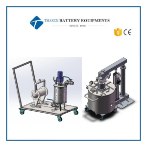 Magnetic De-ironing Filtration System for Battery Electrode Slurry
Magnetic De-ironing Filtration System for Battery Electrode Slurry 1.Introduction This equipment is a specific feeding equipment for lithium ion battery coating machine, which is composed of two parts: turnover barrel + iron removal filter. 2.Standard composition and key configuration table 2.1Turnover barrel and lifting part 1.Feeding barrel Design volume/use volume 150L/100L The material of the inner tank of the mixing tank in contact with the material: 304 stainless steel. Mixing barrel specification About φ650*450 1) Discharge valve: G2” (DN50); 2) The barrel body has push and pull handles, and the barrel bottom has 4 casters (2 orientation + 2 universal); 3) Cooling/heat preservation: with bottom/side wall cooling jacket, cooling water inlet/outlet water distribution pipe union 2.Upper cover Upper cover specification Match with the corresponding mixing tank The material of the part in contact with the material: 304 stainless steel. 1), with 2 small windows, a spotlight, feeding tube DN25 (with 304 ball valve), suction/discharge vacuum interface, vacuum pressure gauge and other spare connections; 2) The upper cover and the mixing barrel are fixed and locked with quick-locking buckles. 1. Mixing accessories and basic parameters Mixing shaft/Mixing paddle speed About 25rpm Material: SUS304 Mixing motor power 1.1kw/4P Reducer(matched with motor) NMRV-090-60-FA-F2-Y90S-1.1KW Mixing paddle form Combined frame type mixing paddle. 4.Mixing principle The combined frame-type mixing paddle performs downward pressure rotation to ensure that the material does not deposit. 5.Vacuum guarantee system: 5 skeleton oil seals are installed in parallel, and the vacuum source is provided by the user 1), the vacuum degree is ≤-0.098Mpa, keep for 24 hours not less than -0.08Mpa. 2) Sealing method: A, static seal uses "O"-shaped sealing ring; B, skeleton oil seal. 6. Power distribution box: the stirring switch, spotlight switch, emergency stop and other functional operations during equipment operation are all carried out on the power distribution cabinet. 7. Lifting device: 1 φ125x800 lifting cylinder, equipped with 1 safety pin 2.2Iron removal filter part No. Name Material Note 1 Shaft seal Viton Wear-resistant and corrosion-resistant 2 Blade Polyester plastic (imported from UK)Wear-resistant and corrosion-resistant 3 Blade spring SUS304 4 Sealing ring Silica gel 5 Shaft assembly EPDM+SUS304 6 Filter element SUS316 Accuracy deviation value: ±0.03mm (maximum ±0.05mm), diameter deviation value: ±0.3mm 80 mesh to 200 mesh optional (standard 120 mesh) 7 Shell/Upper and Lower Plate Cover/Blade Holder SUS304 8 DC motor 24V/60W 9 Separator pump Aluminum alloyQBY-25 3.Liquid level sensing system Working principle: The liquid level sensor transmits the signal to the solenoid valve according to the change of the material liquid level, and the solenoid valve controls the feeding amount of the pneumatic diaphragm pump, thereby realizing the function of automatic feeding. No. Name Model Quantity Note 1 liquid level sensor Domestic brand 1 2 The electromagnetic valve Taiwan 1 3 Intermediate relay Domestic brand 1 4 Intermediate relay holder Domestic brand 1 5 Rotary Switches Domestic brand 1 4.Principle This equipment is filled with dry compressed air into a sealed pressure barrel, and pressurizes the inner cavity of the pressure barrel to press the slurry into the upper trough of the coating machine.
-
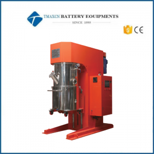 100L Double Planetary Vacuum Mixer for Cathode&Anode Slurry Making
-
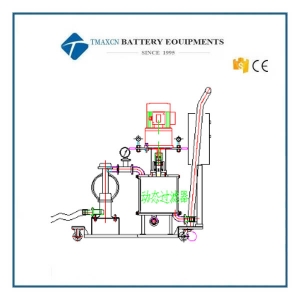 High-Precision Slurry De-ironing Filtration & Transfer System
High-Precision Slurry De-ironing Filtration & Transfer System I. Flow Diagram & Description: #1 Scheme: #2 Scheme: 1. The slurry contained in the transfer tank is conveyed via a diaphragm pump through filtration and iron-removal equipment before being delivered to the coating machine's hopper. 2. All components are interconnected using quick-release couplings and mounted on a stainless steel tray. The slurry transfer process is regulated by the piping network and control system. 3. Crucial Note: The connecting pipeline valves and level control mechanisms between this system and the coating hopper/storage tank must be installed and managed by the end-user and coating machine supplier, as these elements are specifically tailored to your facility and selected coating line configuration. II. Equipment Composition & Capacity: No. Name Model/Specification Unit Qty Remarks 1 Pneumatic double diaphragm pump 3/4″ – S.K.Y. or Graco pcs 1 With standard ISO quick connect 2 Filter cartridge Φ76 × 200 mm pcs 1 100–250 mesh 3 Magnetic rod Φ25 × 156 mm pcs 3 10,000 Gauss each 4 Pressure gauge Ø60 mm – 1 MPa pcs 1 SUS304 stainless steel 5 Squeegee (scraper) 3 piece scraper set pcs 1 Squeegee material: PTFE (Teflon); Spring in Japanese stainless steel 6 Connection tube/valve/fittings Ø25 mm set 1 SUS304 stainless steel 7 Stainless steel tray Non standard (L×W×H) mm pcs 1 SUS304 stainless steel 8 System control cabinet Level, pressure, alarm, control pcs 1 SUS304 stainless steel 9 Conveyance capacity Operating capacity: 20 L/min – – – III. Other Instructions & Cautions: 1. Shaft seal, squeegee, and filter cartridge are consumable parts. 2. This system is intended for a single slurry formulation in continuous production—frequent batch changes or intermittent operation should be avoided. 2 1. When changing slurry types, flush pipes and magnetic filters, and replace key parts (filter cartridge, mesh), and preferably replace piping too. 2 2. During normal operation, ensure the pipelines remain filled with slurry to prevent air ingress and moisture, which can cause slurry solidification. 2 3. External dimensions: 500 mm × 1000 mm × 900 mm (L × W × H).
-
200L Pneumatic Lifter for Mixer
200L Pneumatic Lifter for Mixer I. Equipment Features Application Scope l Lifting the transfer barrel cover assembly. II. Main Equipment Parameters Control System & Performance l Air Pressure: 0.5 – 0.6 MPa (dry compressed air) l Air Consumption: 15 L/min l Lift Control Panel: Manual directional valve with self‑lock l Control Mode: Manual l Rated Load: ≤ 360 kg l Machine Weight: ≈ 420 kg l Dimensions: L 1290 × W 1220 × H 1691 mm (raised 2491 mm) l Color: Off‑white l Floor Load: 400 kg/m² III. Key Components Brand No. Item Spec. Material Qty Brand 1 Cylinder ΦD × ΦN Al‑alloy 1 Airtac 2 Pneumatic Valve – – 1 Airtac IV. Supporting Conditions No. Item Standard Requirements 1 Workshop Height > 2.5 m; ensure lift clearance 2 Door Size H > 2.0 m; W > 1.0 m 3 Heating Room > 20 °C to keep lubricants fluid 4 Installation Space As per layout 5 Others No corrosive / explosive gases or liquids Slurry De-Ironing, Filtration & Transfer System Model: HDCG-3/4"-3 I. Process Diagram & Description 1. Slurry stored in the transfer tank is pumped (diaphragm pump) through pipelines for filtration & de‑ironing, then delivered to the coating‑machine hopper. 2. All components are connected via quick fittings and fixed on a stainless tray; transfer is managed by the control system & piping. 3. Note: Valve & level‑control between this system and the coating hopper/tank shall be installed and managed by the customer & coater supplier. II. Equipment Configuration & Capacity No. Name Spec. / Model Unit Qty Remarks 1 Pneumatic Diaphragm Pump 3/4" – Skylink or Graco set 1 with ISO quick clamp 2 Filter Cartridge Φ76 × 200 mm (100–250 mesh) pc 1 – 3 Magnetic Bars Φ25 × 156 mm, 10 000 GS pc 3 – 4 Pressure Gauge Φ60, 0–1 MPa, SUS304 pc 1 – 5 Scraper Assembly Triple‑blade, PTFE scrapers / SS springs set 1 – 6 Tubes & Valves Φ25, SUS304 set 1 – 7 Stainless Tray Custom size (L × W × H) pc 1 SUS304 8 Control Box Level, pressure, alarm, control pc 1 SUS304 9 Transfer Capacity 20 L/min – – working flow III. Additional Notes & Precautions 1. Shaft seals, scrapers, and filter elements are consumables. 2. System is intended for single‑slurry, continuous production; frequent formulation change or batch interruption is discouraged. 3. When changing material system, clean lines & magnetic filter and replace key parts (filters), preferably new tubing. 4. Keep pipelines filled with slurry to avoid air/moisture ingress that may cause gelation. 5. Overall Dimensions: L 500 × W 1000 × H 900 mm
 +86 13174506016
 David@tmaxcn.com

